Self-biased constant-current voltage stabilizing circuit

A voltage stabilizing circuit and self-biasing technology, which is applied in the field of electrical signal processing, can solve problems such as low input impedance of rectifier circuits, amplitude modulation signal loss, etc., and achieve the effects of simple circuit structure, signal loss reduction, and simplified circuit structure

Inactive Publication Date: 2014-07-16
SHANGHAI HUAHONG INTEGRATED CIRCUIT
View PDF8 Cites 2 Cited by
  • Summary
  • Abstract
  • Description
  • Claims
  • Application Information

AI Technical Summary

Problems solved by technology

However, this solution also has a disadvantage, that is, the shunt regulator will cause the input impedance of the rectifier circuit to be too low, resulting in a very large loss of the AM signal on the antenna, which may affect the sensitivity of the demodulator or the waveform of the card reader. Modulation puts forward higher requirements

Method used


Image

  • Self-biased constant-current voltage stabilizing circuit
  • Self-biased constant-current voltage stabilizing circuit

Examples


Embodiment Construction

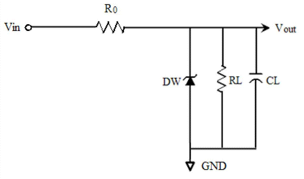
[0014] figure 1 It is the schematic diagram of the existing voltage regulator circuit. Its working principle is that the characteristic of the voltage stabilizing device (as shown in the figure, Zener tube or Zener tube DW) is that when the voltage at both ends reaches the voltage regulation value (set to Vw), it can absorb any large Current (within the rated power range) and the voltage hardly rises, so when the input voltage Vin is higher than the regulated value Vw, no matter how the input voltage Vin rises, the voltage across the voltage regulator device is always stable at the regulated value Vw, and The excess voltage will drop across resistor R0.

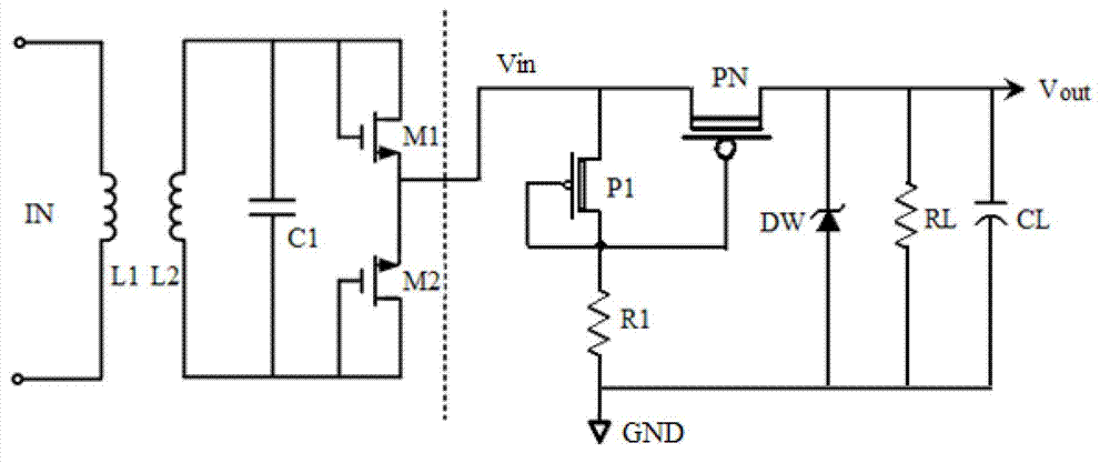
[0015] see figure 2 As shown, in the following examples, the self-biased constant current regulator circuit, in figure 1 Improvements are made on the basis of the voltage stabilizing circuit shown to form an improved self-bias constant current voltage stabilizing circuit; including: input signal detection module, series c...


PUM


Abstract

The invention discloses a self-biased constant-current voltage stabilizing circuit. The self-biased constant-current voltage stabilizing circuit comprises an input signal detection module, a series constant-current tube and a shunt adjustor, and a second resistor and a capacitor, wherein the input signal detection module is connected between an input voltage end and the ground; the series constant-current tube is connected between the input voltage end and an output voltage end, and used for controlling all or a part of channels for inputting signals to an output end; the shunt adjustor is connected between the output voltage end and the ground; the second resistor and the capacitor are connected between the output voltage end and the ground respectively. The self-biased constant-current voltage stabilizing circuit disclosed by the invention is capable of furthest absorbing the current provided by a rectifier and ensuring no weakening for an amplitude-modulated signal on an antenna.

Description

technical field [0001] The invention relates to the field of electrical signal processing, in particular to a self-bias constant current voltage stabilizing circuit. Background technique [0002] In the field of RFID (radio frequency identification), the contactless card needs to restore the command of the card reader and obtain energy for the on-chip circuit from the radio frequency signal emitted by the card reader at the same time. The process of obtaining energy is to rectify the signal induced on the antenna to obtain a DC power supply, and the process of reading the command is to demodulate the envelope of the obtained induction signal. A problem encountered in the power generation process is that the carrier amplitude on the antenna will fluctuate greatly with different distances and working conditions. In order to make the on-chip circuit work stably, it is generally necessary to stabilize the rectified voltage. The traditional PMOS LDO (low dropout linear regulator...

Claims


Application Information

Patent Timeline
Patent Type & Authority Applications(China)
IPC IPC(8): G05F1/56
Inventor 王光春
Owner SHANGHAI HUAHONG INTEGRATED CIRCUIT
Why Eureka
Try Eureka