
Array substrate, manufacturing method of array substrate and display panel

A technology for array substrates and base substrates, which is applied in the fields of array substrates and their preparation methods and display panels, can solve the problems of complex manufacturing processes and high production costs, and achieve the effects of simplifying manufacturing processes, reducing production costs, and reducing process manufacturing time

Active Publication Date: 2014-07-16
BOE TECH GRP CO LTD +1
View PDF4 Cites 18 Cited by
  • Summary
  • Abstract
  • Description
  • Claims
  • Application Information

AI Technical Summary

Problems solved by technology

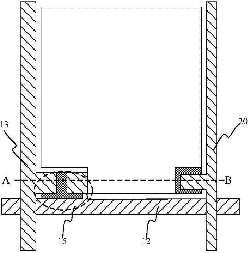
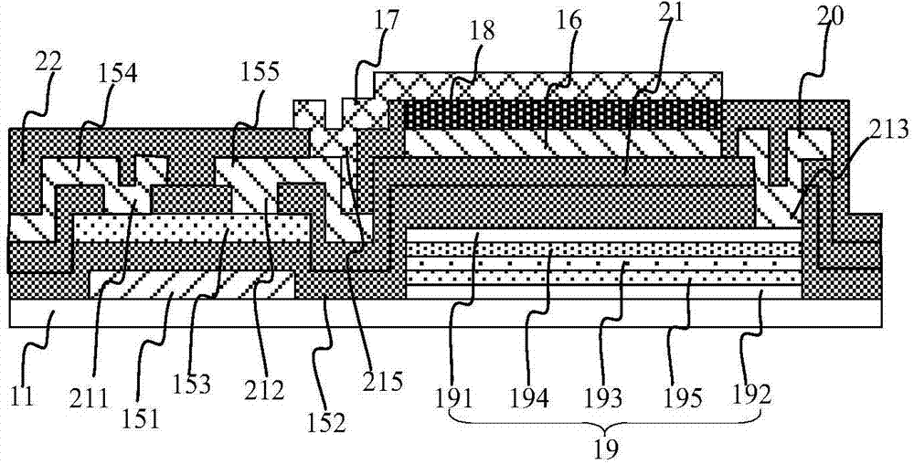
[0005] The embodiment of the present invention provides an array substrate and its preparation method and a display panel, which are used to combine the manufacturing process of the solar cell structure with the manufacturing process of the OLED, realize the combination of the solar energy technology and the OLED display technology, and solve the existing problems. Due to the independent existence of the solar structure and the OLED structure in the technology, the manufacturing process is complicated and the production cost is high.

Method used


Image

  • Array substrate, manufacturing method of array substrate and display panel
  • Array substrate, manufacturing method of array substrate and display panel
  • Array substrate, manufacturing method of array substrate and display panel

Examples


Embodiment Construction

[0048] Embodiments of the present invention provide an array substrate and its preparation method and a display panel, which are used to combine the manufacture of solar cell structures with the manufacture of OLEDs to realize the combination of solar technology and OLED display technology, so as to solve the problems in the prior art. Due to the independent existence of the solar structure and the OLED structure, the manufacturing process is complicated and the production cost is high.

[0049] The following will clearly and completely describe the technical solutions in the embodiments of the present invention with reference to the accompanying drawings in the embodiments of the present invention. Obviously, the described embodiments are only some, not all, embodiments of the present invention. Based on the embodiments of the present invention, all other embodiments obtained by persons of ordinary skill in the art without making creative efforts belong to the protection scope...


PUM


Abstract

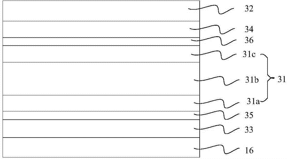
The invention provides an array substrate, a manufacturing method of the array substrate and a display panel. The manufacturing of a solar cell structure and the manufacturing of OLEDs are combined together, so that the solar technology and the OLED display technology are combined, and the problems that as a solar structure and an OLED structure are independent in the prior art, the manufacturing process is complex and the production cost is high are solved. The array substrate comprises a lining substrate, a scanning line, a data line thin film transistor, a public electrode and a pixel electrode, and further comprises a light emitting structure, the solar cell structure and a power output line, wherein the light emitting structure is used for providing a backlight source. The light emitting structure is arranged between the public electrode and the pixel electrode. The solar cell structure is arranged between the lining substrate and the public electrode. The power output line and the public electrode are arranged at the same layer. The power output line is electrically connected with the solar cell structure and transmits electric energy generated by the solar cell structure to an external circuit.

Description

technical field [0001] The invention relates to the technical field of liquid crystal display, in particular to an array substrate, a preparation method thereof, and a display panel. Background technique [0002] Compared with the traditional liquid crystal display (Liquid Crystal Display, LCD) device, the organic light-emitting diode (Organic Light-Emitting Diode, OLED) display device does not require a backlight module, but is made of a very thin light-emitting structure and a glass substrate. Generally, the light-emitting structure includes a light-emitting material layer, an electron transport layer, and a hole transport layer. The electron transport layer and the hole transport layer are respectively arranged on the upper side and the lower side of the light-emitting material layer. layer, the light-emitting structure will emit light. Since the OLED display device does not need a backlight module, the OLED display device can be made lighter and thinner, has a larger vi...

Claims


Application Information

Patent Timeline
Patent Type & Authority Applications(China)
IPC IPC(8): H01L27/12H01L27/32
CPCH01L29/78696H01L27/1214H01L27/1248H01L27/1259Y02E10/547Y02E10/548H10K59/60H10K71/00H10K71/20H10K59/131H10K59/124H10K59/1213H10K59/1201H01L27/12H01L29/41733H01L31/028H01L31/075H01L31/1804
Inventor 张家祥郭建陈旭
Owner BOE TECH GRP CO LTD
Learn More