Welding process of plunger assembly of hydraulic buffer

A hydraulic buffer and welding process technology, applied in welding equipment, welding medium, welding equipment, etc., can solve the problems of high labor intensity of operators, uneven welding seam, low welding efficiency, etc., and achieve beautiful appearance and uniform welding seam , the effect of improving the pass rate

Inactive Publication Date: 2014-07-23
上海青浦电梯配件有限公司
View PDF0 Cites 1 Cited by
  • Summary
  • Abstract
  • Description
  • Claims
  • Application Information

AI Technical Summary

Problems solved by technology

[0007] The above welding process is not only labor-intensive for operators, but also the weld seam is uneven and the welding efficiency is low

Method used


Image

  • Welding process of plunger assembly of hydraulic buffer

Examples


Embodiment Construction

[0022] The present invention will be further described below in conjunction with accompanying drawing.

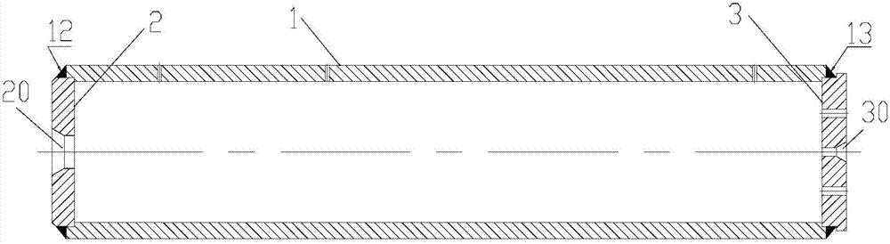
[0023] see figure 1 , The plunger assembly of the hydraulic buffer is composed of a plunger 1, a base plate 3, and a seat plate 2 welded together. The base plate 3 and the seat plate 2 respectively have a central hole 30, 20 coaxial with the plunger 1.

[0024] The welding process of the plunger assembly of the hydraulic buffer of the present invention is operated by a robot holding a welding machine on the welding tool. The welding tooling includes left thimble, right thimble and auxiliary support. The left thimble is installed on a tailstock that can move axially along the guide rail to adapt to the diversity of product lengths. The left thimble is a flexible thimble. The guide rail is equipped with a guide rail brake system. In order to lock the position of the tailstock after adjusting the thimble at the left end. The thimble at the right end is installed on the outpu...


PUM


Abstract

The invention discloses a welding process of a plunger assembly of a hydraulic buffer. The welding process comprises the following steps that firstly, a bottom plate and a base are correspondingly arranged in a left end hole and a right end hole of a plunger one to one, so that a plunger assembly to be welded is formed; secondly, the plunger assembly to be welded is placed on an auxiliary support of a welding tool, then the height of the auxiliary support is adjusted, a right-end ejector pin abuts against a central hole of a base plate, and a left-end ejector pin abuts against a central hole of the bottom plate; thirdly, a welding control button is started, a welding nozzle of a welder is made to get close to the welding position, at the left end, of the bottom plate and the plunger first, arc starting is conducted, meanwhile a servo motor on the welding tool drives the plunger assembly to rotate, welding is conducted in a circle, a robot is made to turn around, the welding nozzle of the welder is made to get close to the right end, and the welding position of the base plate and the plunger is welded automatically. According to the welding process, clamping time and welding time can be shortened, welding performance is stable, welding quality is high, and work efficiency is high.

Description

technical field [0001] The invention relates to a welding process of a plunger assembly of a hydraulic buffer. Background technique [0002] The plunger assembly of the hydraulic buffer is composed of plunger 1, bottom plate 3 and seat plate 2 welded (see figure 1 ), the bottom plate 3 and the seat plate 2 are installed in the holes at both ends of the plunger 1 respectively, and the bottom plate 3 and the seat plate 2 respectively have a central hole 30, 20 coaxial with the plunger 1. The welding position of the plunger assembly is in a circle where the bottom plate 3, the seat plate 2 and the plunger 1 are joined. The height of the welding joints 12 and 13 is 5mm. The surface of the welding seam should be full and uniform by visual inspection, without defects such as virtual welding, desoldering, air holes, overburning, undercut, etc., and there should be no excessive accumulation at the end. The quality of the welding process of the plunger assembly directly affects the...

Claims


Application Information

Patent Timeline
Patent Type & Authority Applications(China)
IPC IPC(8): B23K9/16B23K9/32B23K9/12B23K37/053
CPCB23K9/16B23K9/028B23K9/12B23K35/383B23K37/0426
Inventor 汪国爱黄强
Owner 上海青浦电梯配件有限公司
Why Eureka
Try Eureka