Multifunctional automobile braking system

A car braking system and multi-functional technology, applied in the field of car braking systems, can solve problems such as inability to act immediately, high manufacturing cost, and complicated operation, so as to increase parking braking force, reduce driving difficulty, and reduce manufacturing costs Effect

Active Publication Date: 2014-07-23
GREAT WALL MOTOR CO LTD
View PDF8 Cites 7 Cited by
  • Summary
  • Abstract
  • Description
  • Claims
  • Application Information

AI Technical Summary

Problems solved by technology

[0002] Existing automobiles are generally equipped with separate service brake systems and parking brake systems, wherein the service brake system simultaneously brakes the front and rear wheels of the vehicle (such as the brake system disclosed in the invention patents with application numbers 200910224130.2 and 200910167078.1 ), while the parking brake system only brakes the rear wheels of the vehicle (such as the parking brake system disclosed in the invention patent with application number 200880107426. The problem of insufficient braking force cannot guarantee the safety of vehicles and pedestrians
[0003] Most of the existing automatic parking systems are electric caliper or electric pull-wire parking systems, and their basic components include electric force applying mechanism, deceleration mechanism, etc., and the manufacturing cost is relatively high
Moreover, the operation is relatively complicated, and it cannot act immediately after stepping on the brake pedal, which increases the driving difficulty of the driver and cannot realize real automation.
In addition, the existing automatic parking system cannot release the brake under certain working conditions (such as vehicle power shortage, etc.), which brings inconvenience to the use of the vehicle

Method used


Image

  • Multifunctional automobile braking system
  • Multifunctional automobile braking system
  • Multifunctional automobile braking system

Examples


Embodiment Construction

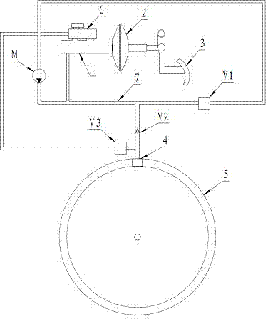
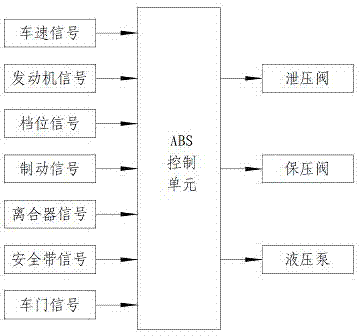
[0015] see figure 1 with figure 2 , the present invention includes a brake master cylinder 1, a vacuum booster pump 2, a brake pedal 3, a brake 4, a liquid storage tank 6, a brake pipe 7, a hydraulic pump M, a pressure relief valve V1, a pressure maintaining valve V2, a parking brake Automatic release valve V3, oil pipe and ABS control unit.

[0016] working principle:

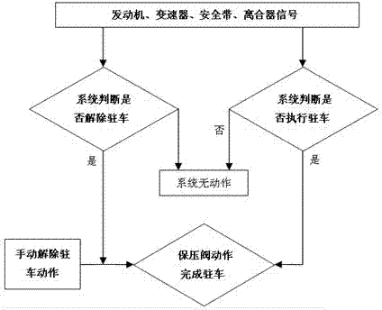
[0017] The system is based on the ABS system (or ESP system), in which all wheels are braked, and the braking force of each wheel can be independently controlled ( figure 1 Only one wheel is drawn in the figure, and the brakes of the rest of the wheels are the same), the parking brake system and the service brake share the same set of brake system, when the brake pedal is stepped on, the brake master cylinder 1 works, and the system Work in the service braking mode; when the system receives the parking signal, the hydraulic pump M starts to work; when the braking pressure of a wheel reaches the calculated ...


PUM


Abstract

A multifunctional automobile braking system comprises a braking main cylinder, a vacuum booster pump, a brake pedal, a brake, a hydraulic pump, a decompression valve and a pressure retaining valve. The brake pedal drives the braking main cylinder through the vacuum booster pump. The braking main cylinder is connected with the brake for front wheels and rear wheels through a brake pipe. The pressure retaining valve is arranged on the brake pipe. An oil suction opening of the hydraulic pump is connected with a liquid storage tank on the braking main cylinder through an oil pipe. An oil outlet of the hydraulic pump is connected with the portion, between the braking main cylinder and the pressure retaining valve, of the brake pipe. One end of the pressurization pump is connected with the portion, between the braking main cylinder and the pressure retaining valve, of the brake pipe, and the other end of the pressurization pump is connected with the liquid storage tank on the braking main cylinder through an oil pipe. According to the multifunctional automobile braking system, a driving braking system, a parking braking system and an emergency braking system are integrated, manufacturing cost of the braking system is reduced, and due to the fact that the front wheels and the rear wheels are simultaneously braked, the parking braking force of an automobile is increased, and safety of the automobile and safety of pedestrians are ensured.

Description

technical field [0001] The invention relates to an automobile brake system integrating the functions of driving brake, emergency brake and parking brake, and belongs to the technical field of automobiles. Background technique [0002] Existing automobiles are generally equipped with separate service brake systems and parking brake systems, wherein the service brake system simultaneously brakes the front and rear wheels of the vehicle (such as the brake system disclosed in the invention patents with application numbers 200910224130.2 and 200910167078.1 ), while the parking brake system only brakes the rear wheels of the vehicle (such as the parking brake system disclosed in the invention patent with application number 200880107426. The problem of insufficient braking force cannot guarantee the safety of vehicles and pedestrians. [0003] Most of the existing automatic parking systems are electric calipers or electric pull-wire parking systems, and their basic components incl...

Claims


Application Information

Patent Timeline
Patent Type & Authority Applications(China)
IPC IPC(8): B60T8/38B60T13/60
Inventor 段志相王超刘盼娜
Owner GREAT WALL MOTOR CO LTD
Why Eureka
Try Eureka