
Bearing ring and sleeve part automatic quenching machine based on robot control

A bearing ring and robot technology, applied in the direction of heat treatment process control, manufacturing tools, furnace types, etc., can solve the problems of high production cost, high labor intensity of manual operation, and high labor intensity, so as to promote the lean production process, avoid Leakage of quenching liquid and the effect of improving quenching quality

Inactive Publication Date: 2014-07-23
DONGHUA UNIV
View PDF4 Cites 4 Cited by
  • Summary
  • Abstract
  • Description
  • Claims
  • Application Information

AI Technical Summary

Problems solved by technology

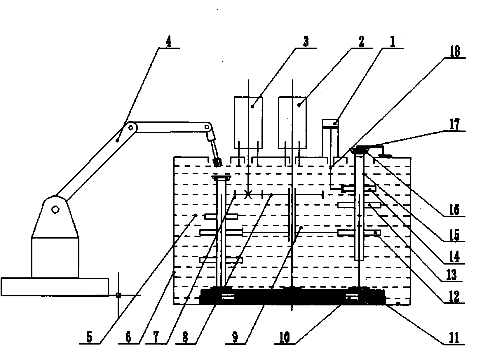
[0005] The external motor of the quenching machine drives an independent transmission shaft. The transmission shaft passes through the bottom of the quenching tank from below. The transmission shaft and the bottom of the quenching tank use rolling bearings and sealing rings to drive the quenching device. Undertake the task of multi-station rotation, but also move up and down due to the two processes of heating and quenching, so the bearing sealing ring installed between the bottom of the water tank and the transmission shaft is easy to wear due to frequent rotation and movement, and often occurs sealing Ineffective, the quenching liquid is easy to leak from the gap between the moving pair between the water tank and the transmission shaft, resulting in frequent shutdowns and production accidents, which brings great inconvenience to the production site
[0006] 2. Manual operation is labor-intensive:
[0007] The loading and unloading operation of quenching is completely manual operation, the workers repeat the operation, the labor intensity is high, and it is easy to cause operational errors in the process of heating, quenching, loading and unloading, etc., the quality of quenching cannot be guaranteed, the production efficiency is low, and the production cost remains high

Method used


Image

  • Bearing ring and sleeve part automatic quenching machine based on robot control
  • Bearing ring and sleeve part automatic quenching machine based on robot control
  • Bearing ring and sleeve part automatic quenching machine based on robot control

Examples


Embodiment Construction

[0028] In order to make the present invention more comprehensible, preferred embodiments are described in detail below with accompanying drawings.

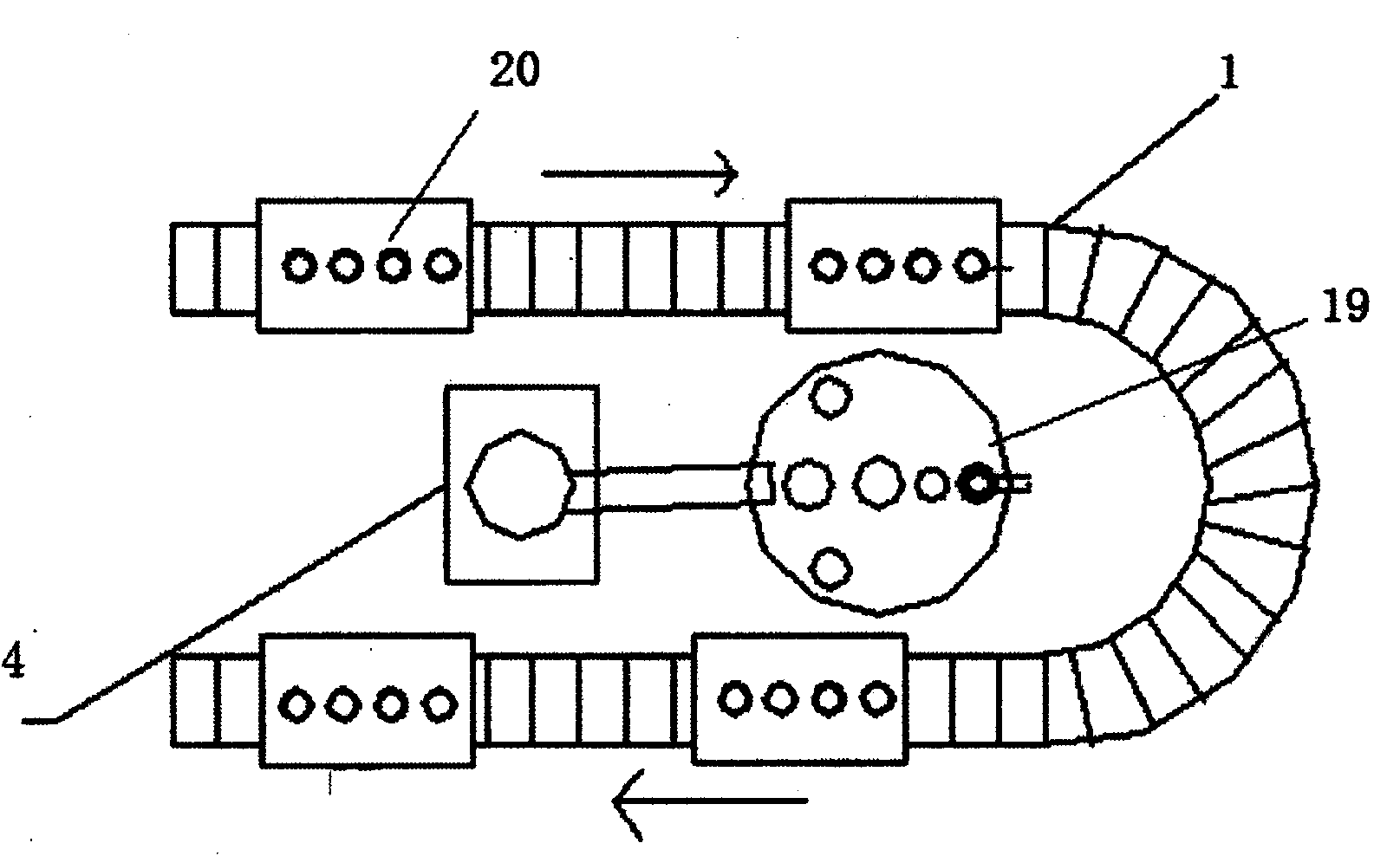
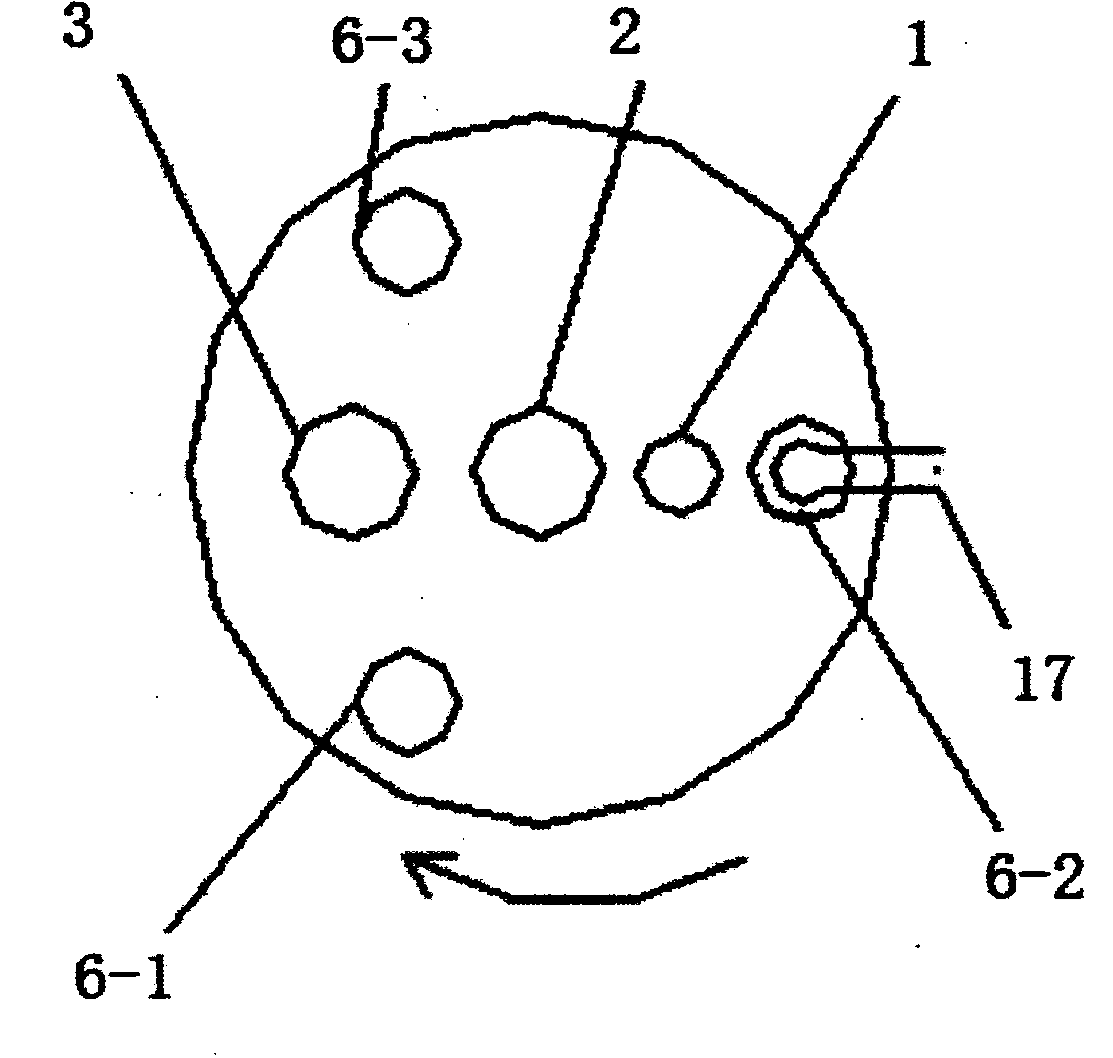
[0029] Such as figure 1 As shown, the present invention provides a robot-based automatic quenching machine for bearing rings and sleeve parts, which includes three subsystems in total, which are RGV automatic guided transport vehicle system 1, robot 4, quenching equipment and control sub-systems. System 19, wherein:

[0030] The parts 16 to be processed (in this embodiment, the parts 16 are bearings) are placed on the RGV trolley 20 of the RGV automatic guided vehicle system 1, and the automatic transportation of the parts to be processed 16 is realized by the RGV automatic guided vehicle system 1;

[0031] The robot 4 grabs the bearing to be processed on the RGV trolley 20 and puts it into the quenching equipment and the control subsystem 19. The quenching equipment and the control subsystem 19 complete the heating and quenching...


PUM


Abstract

The invention relates to a bearing ring and sleeve part automatic quenching machine based on robot control. The quenching machine is characterized by comprising an RGV (Rail Guided Vehicle) automatic guiding transport trolley system, a robot, quenching equipment and control sub-system, wherein a to-be-processed part is placed on an RGV trolley of the RGV automatic guiding transport trolley system to automatically transport the to-be-processed part; the robot grasps the to-be-processed part on the RGV trolley and puts the to-be-processed part in the quenching equipment and control sub-system to heat and quench the to-be-processed part; and then, the robot takes the quenched part from the quenching equipment and control sub-system on the RGV trolley. The invention provides a bearing inner and outer ring automatic quenching system which not only can save the cost, but also can further improve the efficiency and the quenching quality and is in butt joint and integrated with the flexible manufacturing systems of the enterprise.

Description

technical field [0001] The invention relates to an automatic quenching machine for bearing rings and sleeve parts based on robot control, which can realize the production processes of feeding, loading, heating, quenching, unloading and discharging of bearing inner and outer rings and rotary sleeve parts. It is widely used in the flexible processing automatic production line of the quenching process of bearing rings and rotary parts, and realizes the docking and integration of the factory quenching flexible manufacturing system. Background technique [0002] Rolling bearings are key components of general and special machinery, mainly composed of bearing outer rings, inner rings, rollers, cages, etc. The precision and wear resistance of the bearing directly affect the motion precision and life of the machine. To ensure high hardness and wear resistance of high bearings, quenching of bearing rings is an essential link. [0003] At present, in order to save costs, many domesti...

Claims


Application Information

Patent Timeline
Patent Type & Authority Applications(China)
IPC IPC(8): C21D9/40C21D11/00
Inventor 闫如忠贾俊阳王建康闫夙祝贺林宇超易涛熊学文田林林杨旭
Owner DONGHUA UNIV
Learn More