Floating type wave energy power generation device by using piston to pressurize water turbine to generate electricity

A technology of power generation device and supercharging device, which is applied in the direction of ocean energy power generation, components of pumping devices for elastic fluids, machines/engines, etc., and can solve the problem of complex structure, high manufacturing cost and maintenance cost of wave energy power generation devices, Low utilization rate of wave energy and other issues, to achieve the effect of short energy conversion process, reduced maintenance cost, and simple structure

Active Publication Date: 2014-07-23
LOGISTICAL ENGINEERING UNIVERSITY OF PLA +1
View PDF6 Cites 16 Cited by
  • Summary
  • Abstract
  • Description
  • Claims
  • Application Information

AI Technical Summary

Problems solved by technology

[0012] To sum up, the existing wave energy generating devices have complex structure, high manufacturing cost and maintenance cost, low utilization rate of wave energy and low reliability of long-term operation.
[0013] The above-mentioned wave energy generation devices have their own advantages and disadvantages, and they all have the need to improve reliability, improve the utilization rate of wave energy, resist extreme sea conditions, and generate power efficiency.

Method used


Image

  • Floating type wave energy power generation device by using piston to pressurize water turbine to generate electricity
  • Floating type wave energy power generation device by using piston to pressurize water turbine to generate electricity
  • Floating type wave energy power generation device by using piston to pressurize water turbine to generate electricity

Examples


Embodiment Construction

[0027] Below in conjunction with accompanying drawing and embodiment the present invention will be further described:

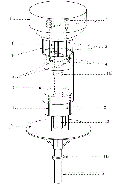
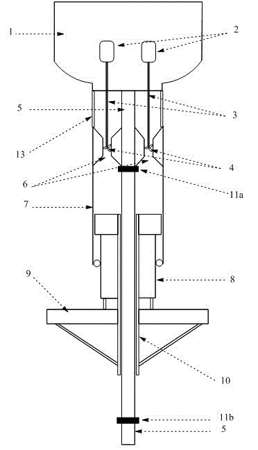
[0028] See attached Figures 1 to 3 , a floating wave energy power generation device for generating electricity by a piston pressurized water turbine, including a generator 2 installed in a floating body 1, and a water turbine 4 connected below the floating body, the piston sleeve is connected below the floating body 1, and there is flowing water on the top Channel 6, seawater can enter the barrel through the water channel 6; the water turbine 4 is located in the water channel 6 on the top of the piston sleeve 7, and is connected to the generator 2 in the floating body 1 through the energy output shaft 3.

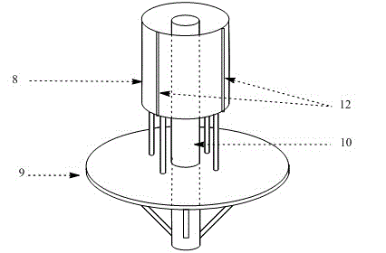
[0029] A central guide shaft 5 is installed at the bottom of the floating body 1, and the central guide shaft 5 passes through the piston sleeve 7 below the floating body 1 and the piston 8 cooperating with the piston sleeve 7. Two limit devices 11a, 11b,...


PUM


Abstract

The invention relates to wave energy power generation devices, and provides a floating type wave energy power generation device by using a piston to pressurize water turbine to generate electricity. The floating type wave energy power generation device comprises an electric generator mounted in a floating body, the water turbine and a piston pressurization system, wherein the water turbine and the piston pressurization system are connected to the lower portion of the floating body. The water turbine is placed in a water channel in the top of a piston sleeve, and is connected with the electric generator through an energy output shaft. A center guide shaft is mounted in the piston sleeve, two limiting devices are mounted on the center guide shaft, and the piston is mounted on the center guide shaft between the two limiting devices through the center shaft sleeve. The piston moves up and down along the center guide shaft under the action force of waves, the piston pushes seawater in an inner cavity in the piston sleeve to flow through the water channel to repeatedly impact vanes of the water turbine to rotate, and the electric generator is driven to generate electricity. Due to the structure, the wave energy power generation device has the advantages that the structure is simple, the manufacturing cost and the maintaining cost are low, and the wave energy utilization rate and the long-term operation reliability are improved.

Description

technical field [0001] The invention relates to a wave energy generating device, in particular to a wave energy generating device with simple structure, low manufacturing cost and maintenance cost, high wave energy utilization rate and long-term operation reliability. technical background [0002] The national economy continues to grow at an annual rate, and correspondingly, this economic growth will inevitably lead to an increase in the demand for energy, especially the increase in demand for electricity. [0003] The existing power generation methods mainly include thermal power, hydropower, nuclear power, etc. Since the development of hydropower and nuclear power will be restricted by many objective conditions, the proportion of the total power generation in the whole society is still relatively small, and thermal power accounts for 80% of China's total power generation. % share. Because thermal power generation needs to consume a large amount of fossil fuels and emit a ...

Claims


Application Information

Patent Timeline
Patent Type & Authority Applications(China)
IPC IPC(8): F03B13/22F04B53/14F04B53/02
CPCY02E10/30
Inventor 王维俊李滨
Owner LOGISTICAL ENGINEERING UNIVERSITY OF PLA
Why Eureka
Try Eureka