Exhaust pipe structure for road surface snow melting, road surface member for snow melting, and road surface snow melting system

A technology for exhaust pipes and structures, applied in the directions of roads, roads, pavement details, etc., can solve the problems of difficult construction, uneven snow melting, and no special consideration of uneven snow melting, so as to reduce construction time and construction costs, and facilitate construction. The effect of suppressing uneven snow melting

Active Publication Date: 2016-01-27
HOKUSUI SEKKEI CONSUL
View PDF6 Cites 0 Cited by
  • Summary
  • Abstract
  • Description
  • Claims
  • Application Information

AI Technical Summary

Problems solved by technology

However, in each of the inventions described in the aforementioned Patent Document 1 to Patent Document 3, they do not focus on solving the problem of uneven snowmelt on the road surface, and neither describe nor suggest it.
For example, in Patent Document 1, there is the following problem: in the vicinity of the opening end of the heat supply pipe that feeds air into the cylindrical structure, and in the vicinity of the soil retaining plate on the back side of the cylindrical structure, the air discharged from the opening air volume makes a big difference
Therefore, the road surface to be melted cannot be heated uniformly, resulting in uneven melting of snow and low melting efficiency.
[0012] In addition, in the invention described in Patent Document 1, in order to form the convective space, it is necessary to dig deep under the road surface, making construction difficult, and there is also a problem of increasing construction time and construction cost.
[0013] In addition, the invention described in Patent Document 2 also supplies air from the air blower to the exhaust pipe in one direction, and does not particularly consider the unevenness of snowmelt. uneven snowmelt
[0014] Furthermore, in Patent Document 3, there is no description or hint about the arrangement structure etc. in consideration of uneven snowmelt with respect to the piping provided with the discharge holes.

Method used


Image

  • Exhaust pipe structure for road surface snow melting, road surface member for snow melting, and road surface snow melting system
  • Exhaust pipe structure for road surface snow melting, road surface member for snow melting, and road surface snow melting system
  • Exhaust pipe structure for road surface snow melting, road surface member for snow melting, and road surface snow melting system

Examples


Embodiment 1

[0085] Next, an experiment was conducted to investigate the practicality of the function and effect of the exhaust pipe structure 2 for road surface snow melting according to the present invention. In Example 1, the fluid when the plurality of perforated pipes 7, 7 ... of the road surface snow-melting exhaust pipe structure 2 are surrounded in a substantially U-shape or substantially annular to allow ventilation is performed using a fluid analysis program. analyze. The thermal fluid analysis programs used in Example 1 are commercially available SolidWorks and COSMOSFloWorks.

[0086] Figure 8 as well as Figure 9 The analysis model used in the simulation of this Example 1 is shown. These models were modeled using SolidWorks. Figure 8 In the model shown as a comparative example, only one end of a plurality of perforated tubes 7, 7... is connected by a connecting tube 8 for ventilation, and the other end is closed. In addition, one end of the connecting pipe 8 for ventila...

Embodiment 2

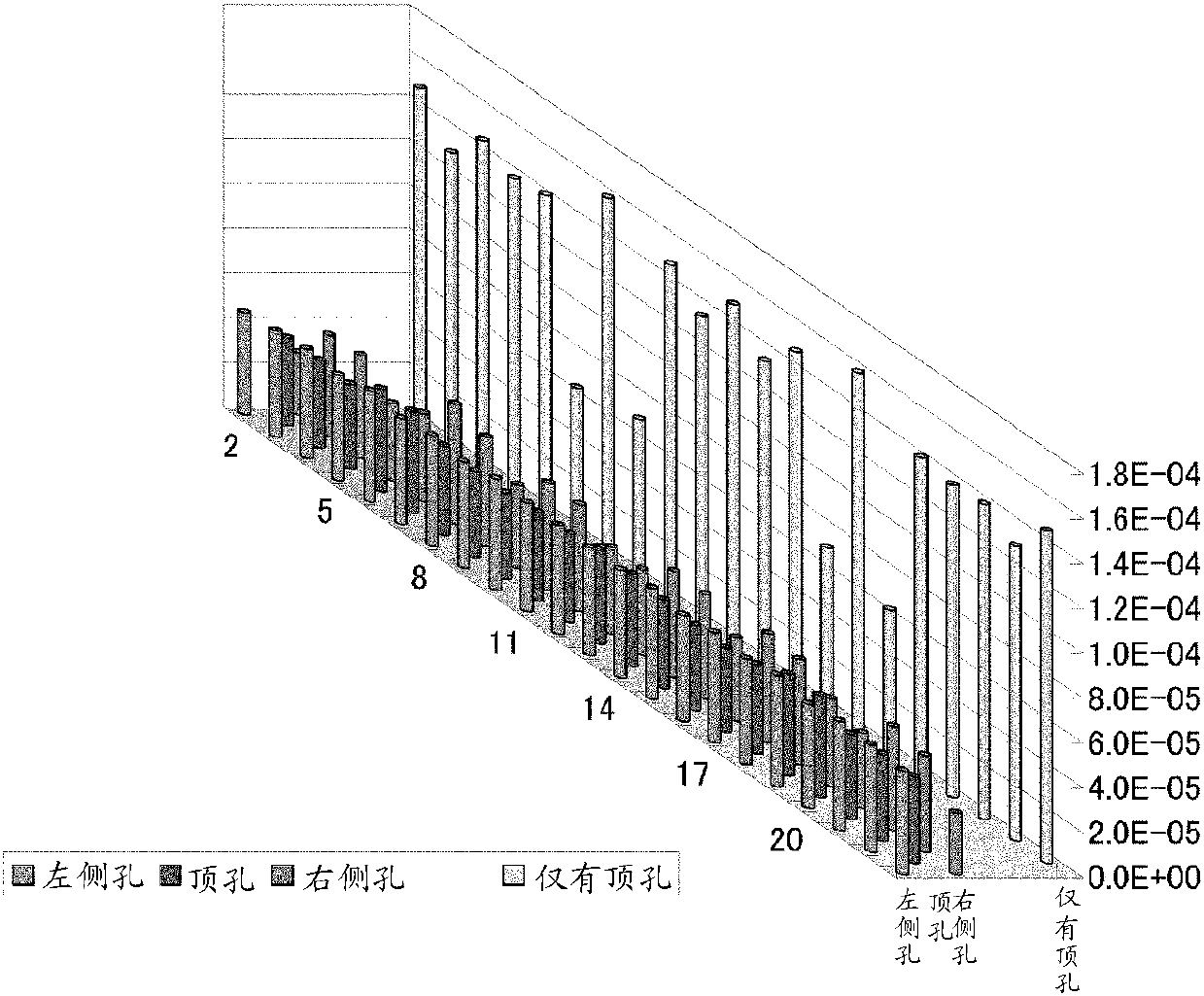
[0106] In Example 2, the number of air ejection holes 6 formed in the perforated tube 7 and the amount of air ejection were simulated using a fluid analysis program. The thermal fluid analysis program used is the same SolidWorks and COSMOSFloWorks as in Example 1.

[0107] Figure 16 as well as Figure 17 The analysis model used in the simulation of this Example 2 is shown. Figure 16 In the model shown, the air ejection hole 6 in the exhaust pipe structure 2 for melting snow on the road surface is constituted only by the top hole 61 . on the other hand, Figure 17In the model shown, the air ejection hole 6 in the exhaust pipe structure 2 for road surface snow melting is composed of a top hole 61 , a right hole 62 , and a left hole 63 .

[0108] Conditions common to each model will be described. First, the length of the perforated pipe 7 is 2300 mm. The number of perforated tubes 7 is two, and they are arranged in parallel at intervals of 300 mm. In addition, the marks ...

Embodiment 3

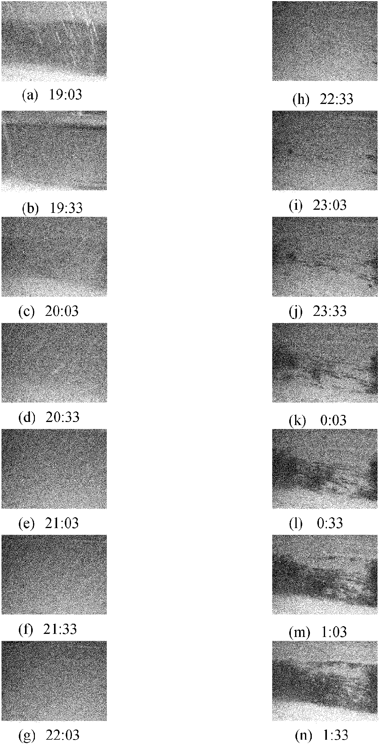
[0119] In Example 3, made Figure 20 The shown road surface snow melting system 1 using the road surface snow melting exhaust pipe structure 2 of the present invention was actually buried under the road surface 5 to conduct a demonstration experiment of the snow melting effect of the road surface snow melting system 1 .

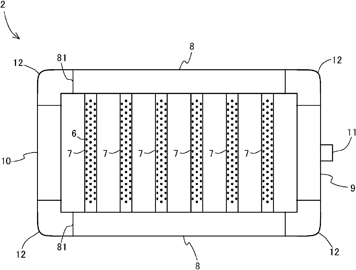
[0120] The exhaust pipe structure 2 for road surface snow melting in the present embodiment 3 is as follows: Figure 21 As shown, a plurality of perforated tubes 7, 7... are surrounded by an air supply tube 9, a pair of connecting tubes 8, 8 for ventilation, and an end ventilation tube 10 in a substantially annular shape so that ventilation is possible. And the range which is the target of snow melting is divided into four blocks, and the exhaust pipe structure 2 for road surface snow melting of a substantially ring shape is arrange|positioned for each block.

[0121] The perforated tube 7 in Example 3 is formed of a polyvinyl chloride tube with an inner dia...


PUM


Abstract

[Problem] Provided are: an air discharge pipe structure for melting snow on a road surface, the air discharge pipe structure being configured so that the air discharge pipe structure can more evenly discharge snow melting air into an area underneath the road surface on which the snow to be melted is present than conventional structures to prevent the uneven melting of the snow, so that the air discharge pipe structure can be built more easily, and so that the air discharge pipe structure can be built in a reduced time and at reduced cost; a road surface material for melting snow; and a system for melting snow on a road surface. [Solution] An air discharge pipe structure for melting snow on a road surface is provided with: perforated pipes (7, 7, ...) which have air ejection holes (6) formed therein and which are laid in a predetermined area underneath the road surface (5) on which the snow to be melted is present; a pair of connection pipes (8, 8) for air flow, connecting the opposite ends of each of the perforated pipes (7, 7, ...) in a pneumatically communicable manner; and an air supply pipe (9) which connects one end of each of the connection pipes (8, 8) for air flow in a pneumatically communicable manner and which is provided with an air supply opening (11) for supplying air. The other end (81) of each of the pair of connection pipes (8, 8) for air flow is connected to each other in a closed state or is connected to each other by an end air-flow pipe (10) in a pneumatically communicable manner.

Description

technical field [0001] The present invention relates to a road surface snow-melting exhaust pipe structure, a snow-melting road surface member, and a road surface snow-melting system that heat the road surface by discharging snow-melting air below the snow-melting target road surface to melt snow. Background technique [0002] Conventionally, various inventions have been proposed regarding a road surface snow melting system, which discharges snow-melting air using waste heat or the like below a road surface to be snow-melted, and heats the road surface with the heat of the air to melt snow. [0003] For example, in Japanese Patent Application Laid-Open No. 2005-36622, a warm-air snow-melting device is proposed, which shields both ends of a cylindrical structure with openings formed on its peripheral surface by a soil shield to form a convective space. The heat supply pipe and the low temperature pipe equipped with an exhaust fan are inserted into the convection space in the ...

Claims


Application Information

Patent Timeline
Patent Type & Authority Patents(China)
IPC IPC(8): E01C11/26
CPCE01C11/26
Inventor 高野义昭大内克行富田和彦平野繁树
Owner HOKUSUI SEKKEI CONSUL
Why Eureka
Try Eureka