

Cleaning trough body structure for photoresist nozzle and application of cleaning trough body structure
A technology for cleaning tanks and nozzles, applied in the directions of cleaning methods, cleaning methods and utensils, chemical instruments and methods using liquids, etc., can solve the problems of increasing material costs, splashing cleaning liquid, increasing the flow of cleaning liquid, etc., to avoid pollution. The effect of preventing residues of contaminants, preventing residues of contaminants, and shortening cleaning time
- Summary
- Abstract
- Description
- Claims
- Application Information
AI Technical Summary
Problems solved by technology
Method used
Image

Examples
Embodiment
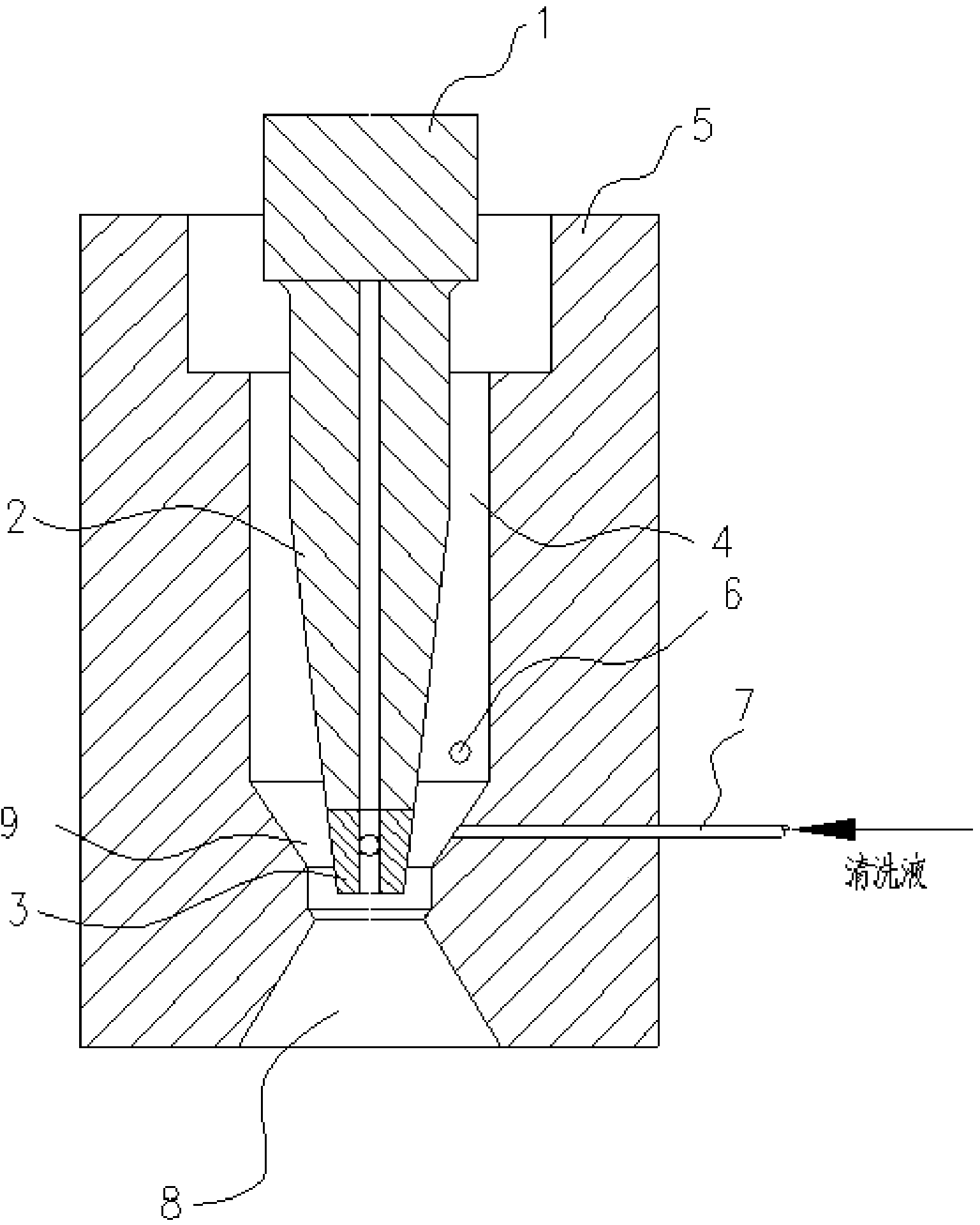
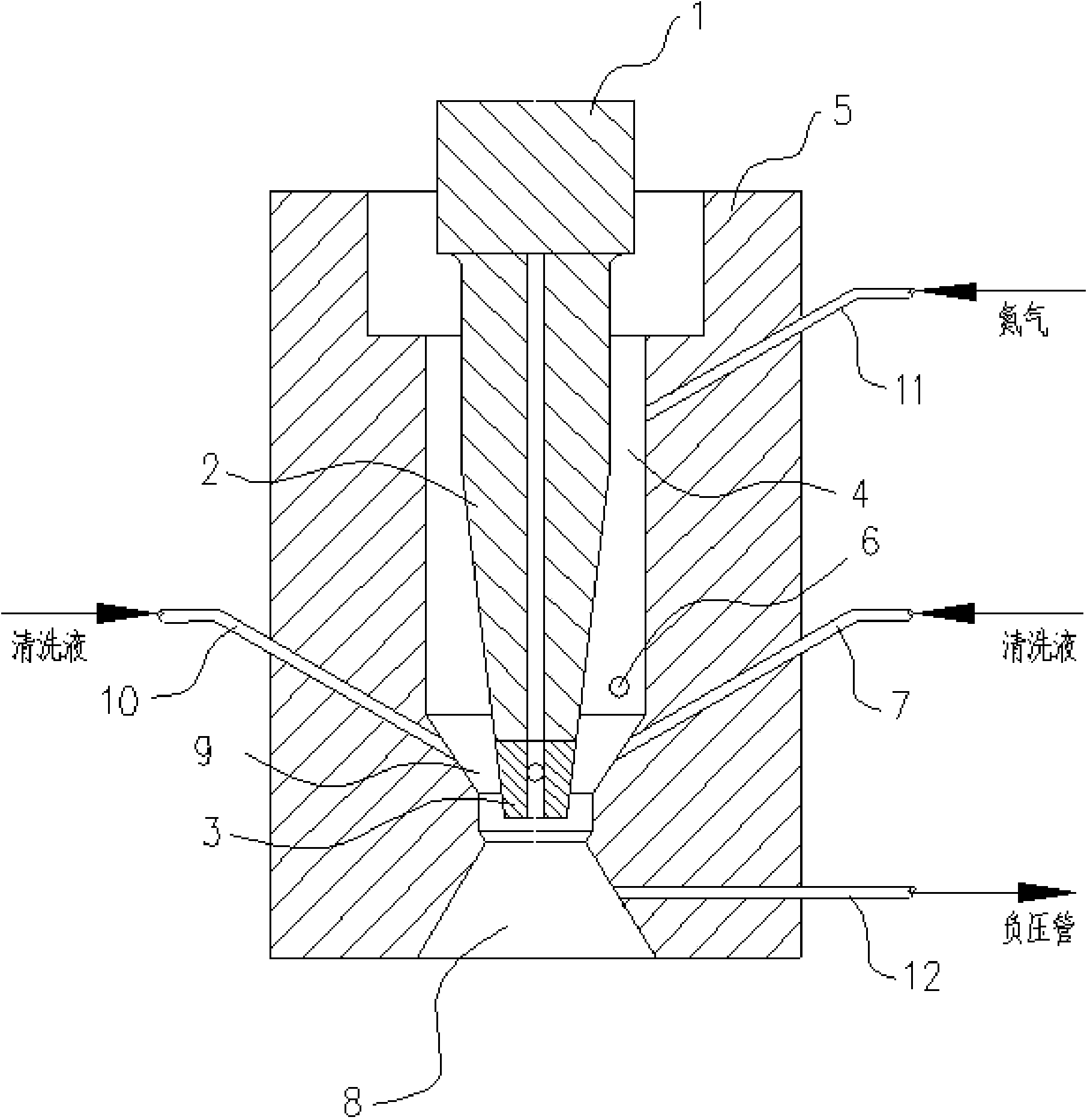
[0043] Such as figure 2 As shown, a cleaning tank structure for photoresist nozzles and its application, including a cleaning tank housing 5, an anti-cleaning liquid splash chamber 4, a nozzle cleaning chamber 9, a cleaning liquid discharge port 8, a nozzle root 1, and a nozzle waist 2. Nozzle head 3, cleaning liquid pipeline 7, final cleaning nozzle 6, the cleaning liquid pipeline 7 passes through the cleaning tank shell 5, and the cleaning liquid is introduced into the nozzle cleaning chamber 9 to rinse the nozzle head 3; the cleaning liquid rinses After the nozzle head 3 is discharged from the cleaning liquid outlet 8, the final cleaning nozzle 6 is used to flush the residual liquid at the outlet of the cleaning liquid pipeline 7 after the nozzle head 3 is cleaned; at least one new cleaning liquid pipe is included Road 10, the outlet of the cleaning liquid pipeline 7 and the newly added cleaning liquid pipeline 10 are evenly distributed on the inner wall of the nozzle clea...
PUM
 Abstract
Description
Claims
Application Information