
Existing engineering pile bottom depth determination method based on parallel seismic inflexion-point method

A technology of side-hole transmitted wave and engineering piles, which is applied in foundation structure engineering, foundation structure testing, construction, etc., can solve the problems of inability to effectively determine the depth of the pile bottom, difficult to determine the depth of the pile bottom, and low depth of exploration holes. It is simple and intuitive to determine the depth of the pile bottom, with good operability and the effect of solving the depth of the pile bottom

Inactive Publication Date: 2014-07-30
SHANGHAI JIAO TONG UNIV +1
View PDF4 Cites 28 Cited by
  • Summary
  • Abstract
  • Description
  • Claims
  • Application Information

AI Technical Summary

Problems solved by technology

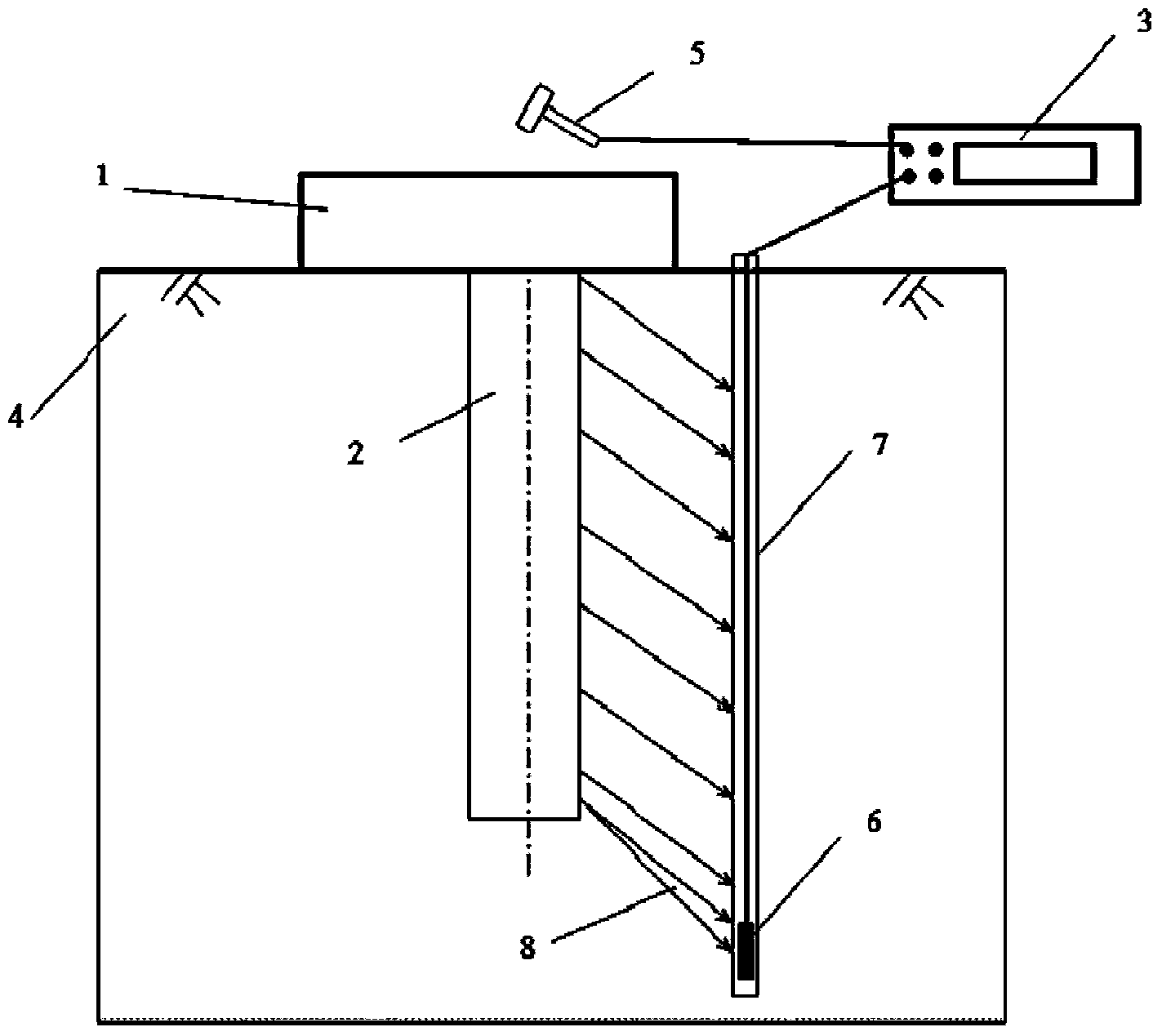
[0006] Aiming at the problem that the current existing engineering piles cannot effectively determine the pile bottom depth, the present invention proposes a method for determining the pile bottom depth of existing engineering piles based on the side hole transmitted wave inflection point method
Compared with the existing side-hole transmission wave intersection method and correction method, which are based on the intersection of two lines to determine the depth of the pile bottom, the side-hole transmission wave inflection point method has lower requirements for the depth of the hole, and has high precision. It is simple and intuitive to determine the position of the inflection point. It only needs to be more than 2-3m below the estimated pile bottom to be tested. It also has good operability for technicians without engineering experience, and it better solves the problem that it is difficult to determine the depth of the pile bottom for existing engineering piles.

Method used


Image

  • Existing engineering pile bottom depth determination method based on parallel seismic inflexion-point method
  • Existing engineering pile bottom depth determination method based on parallel seismic inflexion-point method
  • Existing engineering pile bottom depth determination method based on parallel seismic inflexion-point method

Examples


Embodiment 1

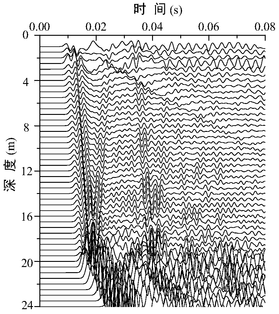
[0026] Such as figure 1 As shown, in this embodiment, the design depth of the pile bottom of the pile to be tested is 20m, and the pile diameter is 0.6m. There is a cap on the top of the pile, and the size of the cap is 3m long, 1m wide and 1m high. The side hole distance D is 2m, the foundation is a uniform unsaturated foundation, and the excitation method is vertical knocking on the cap. The side-hole transmitted wave method detects such as figure 1 As shown, its specific implementation method and steps are:

[0027] 1) Test preparation, clean up the site, drill a hole 2m away from the existing engineering pile to be tested, and put a PVC probe pipe with a diameter of 80mm in the hole. The PVC pipe is arranged along the entire length of the drill hole, and the bottom of the pipe is sealed tightly to prevent water leakage. and sundries, backfill soil around the pipe to make it compact, probe the hole to a depth of 24m, and fill the pipe with clean water.

[0028] 2) Conne...

Embodiment 2

[0036] In this embodiment, the designed depth of the pile bottom to be tested is 39m, and the pile diameter is 1.3m. The top is connected to the bearing platform, of which the thickness of the bearing platform is 0.2m, and the ground of the test site is parallel to the top surface of the bearing platform. A probe hole is arranged at 0.5m from the side of the pile to be tested, the depth of the hole is 46m, and a PVC probe pipe with a diameter of 80mm is lowered in the hole, and the PVC pipe is arranged along the entire length of the borehole. The bottom of the pipe is tightly sealed to prevent water leakage and sundries from entering. After the probe is lowered, it is backfilled so that the outer wall of the probe and the soil layer are closely combined. The side hole transmitted wave inflection point method test is carried out by vertically knocking and vibrating at the position corresponding to the pile on the cap. When testing, place the geophone at the bottom of the hole...


PUM


Abstract

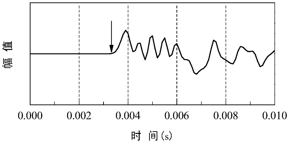
The invention provides an existing engineering pile bottom depth determination method based on a parallel seismic inflexion-point method in the field of civil engineering pile foundation construction quality inspection. Detection is carried out in an exploratory hole after the exploratory hole is drilled beside a pile, a time-depth signal diagram is generated according to different depth signals in the depth direction, an inflection point is determined in the time-depth signal diagram, and the pile bottom depth is obtained after the depth of the inflection point is modified through a inflection-point depth modifier formula. Through the method, the influence on wave form from an upper structure is avoided, the inspection is convenient, and the determination of position of the inflection point is simple and visual. Compared with the conventional parallel seismic method, by which the pile bottom depth is determined based on intersection of two lines, the parallel seismic inflexion-point method has a lower requirement on the depth of the drill hole, just 2-3 m deeper than a pile to be inspected, thereby reducing the requirement on the depth of the exploratory hole, saving cost, having better maneuverability for technical personnel without engineering experience, and better solving the current problem that the pile depth of an engineering pile is hard to determine.

Description

technical field [0001] The invention relates to a method in the field of civil engineering pile foundation engineering quality detection, in particular to a method for determining the pile bottom depth of existing engineering piles based on the side hole transmitted wave inflection point method. Background technique [0002] Existing engineering piles connected to the upper foundation and structure, re-inspection and evaluation in the use state, is still a difficult problem in pile foundation inspection. For old engineering structures, their design or construction records may be difficult to find. If it is necessary to increase the bearing capacity of the bridge pile foundation due to the presence of vehicles with a larger load, it is necessary to check whether the pile foundation is damaged after an earthquake, or under long-term scouring, the soil around the pile is washed away or becomes loose so that the pile foundation When the foundation bearing capacity is reduced, i...

Claims


Application Information

Patent Timeline
Patent Type & Authority Applications(China)
IPC IPC(8): E02D33/00
Inventor 陈龙珠张敬一马晔张理轻杨宇
Owner SHANGHAI JIAO TONG UNIV
Learn More