Testing device and method for monitoring steel wire rope-friction pad dynamic micro-friction state

A friction lining and test device technology, applied in the direction of measuring devices, mechanical devices, instruments, etc., can solve the problems of inability to investigate the dynamic micro-friction behavior of steel wire ropes, and can not explore the dynamic micro-friction behavior, etc., to achieve wide practicability and functionality Complete and effective

Active Publication Date: 2014-07-30
CHINA UNIV OF MINING & TECH
View PDF4 Cites 35 Cited by
  • Summary
  • Abstract
  • Description
  • Claims
  • Application Information

AI Technical Summary

Problems solved by technology

[0003] The friction test device between the wire rope and the pad includes: Patent No. 200510134988.1 discloses a high-speed friction test machine between the wire rope and the pad, which can realize the stepless transformation of different relative sliding speeds between the wire rope and the pad and avoid the wire rope from the drum. Rope skipping phenomenon in the rope groove; Patent No. 201010121802.X published a method and device for measuring the temperature and strain of the sliding friction between the liner and the steel wire rope, realizing dynamic real-time measurement of the temperature and strain of the liner during high and low speed sliding friction; Patent No. 201110436607.0 announced a mine friction hoist liner sliding friction tester, which can study the tribological performance of the liner under different sliding speeds and accelerations when simulating the mine friction hoist sliding; the above patents are all between ste

Method used


Image

  • Testing device and method for monitoring steel wire rope-friction pad dynamic micro-friction state
  • Testing device and method for monitoring steel wire rope-friction pad dynamic micro-friction state
  • Testing device and method for monitoring steel wire rope-friction pad dynamic micro-friction state

Examples


Embodiment Construction

[0023] The present invention will be further explained below in conjunction with the accompanying drawings.

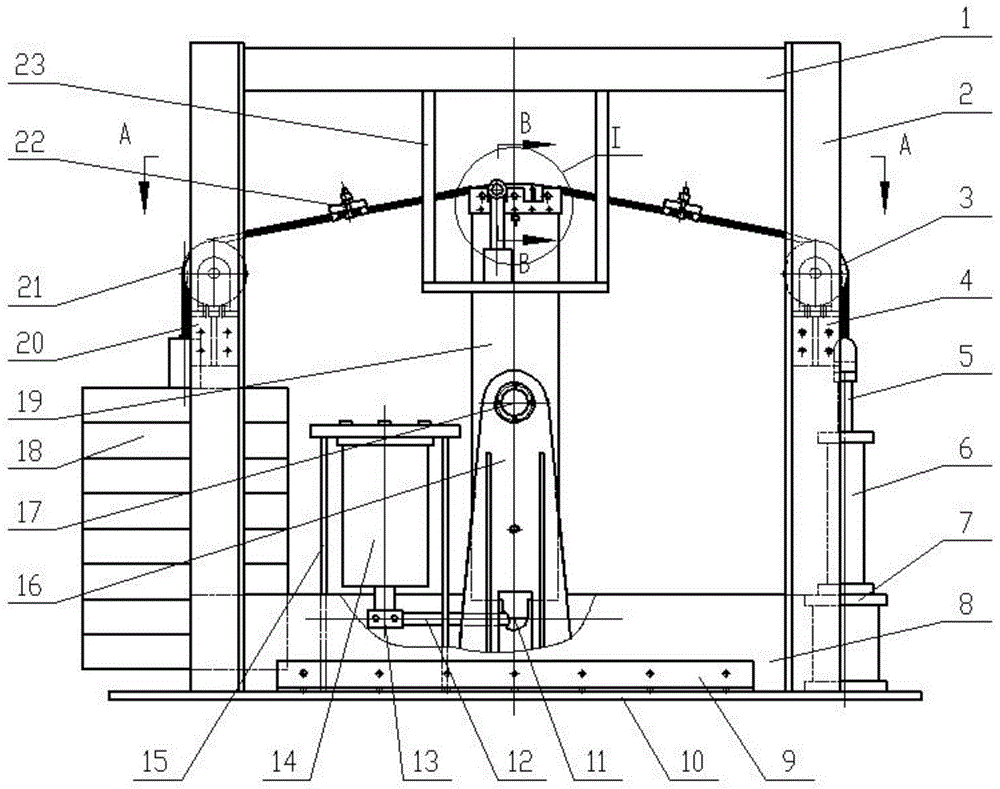
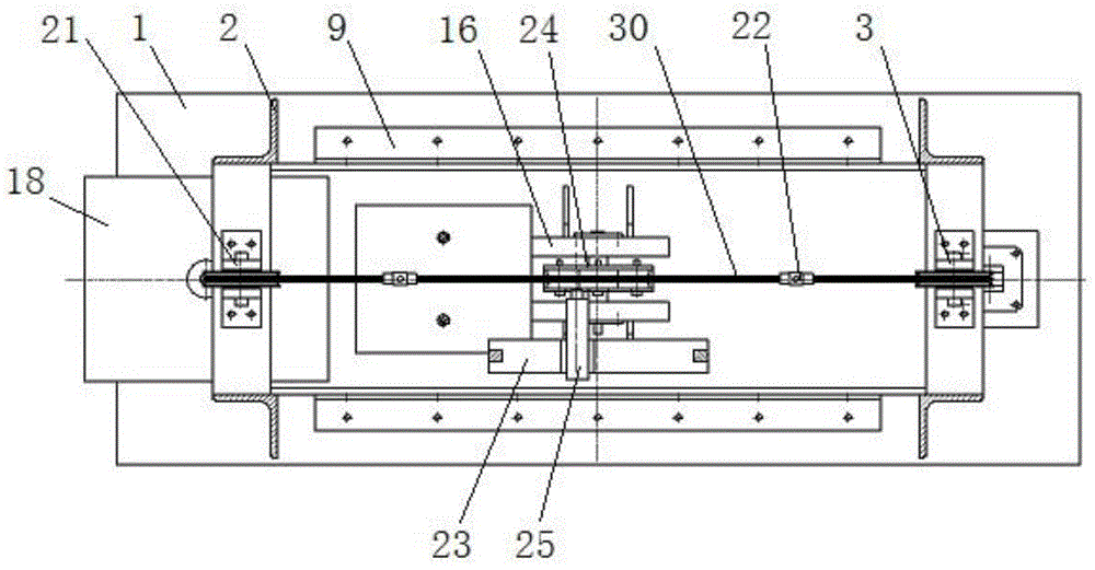
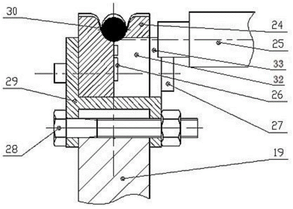
[0024] Such as Figures 1 to 4 As shown, a test device for monitoring the dynamic micro-friction state of the steel wire rope-friction lining of the present invention includes a base frame, a loading system, a micro-slip system and a state monitoring system.

[0025] Described pedestal comprises base plate 10, the support column 2 that is symmetrically arranged on the two ends of base plate 10, the bottom beam 8 that is arranged on support column 2 bottom, is arranged on the fixed angle steel 9 between support column 2 bottom and base plate 10 and is fixed on support column 2 Load beam 1 at the top.

[0026]The loading system includes a weight loading system, a hydraulic loading system and a wire rope 30 . The heavy block loading system includes an A pulley bracket 20 arranged on the support column 2, an A pulley 21 fixed on the A pulley bracket 20, and a weight grou...


PUM


Abstract

The invention discloses a testing device and a testing method for monitoring steel wire rope-friction pad dynamic micro-friction state. The testing device comprises a base frame, a loading system, a micro-slip system and a state monitoring system, wherein the loading system comprises a weight loading system, a hydraulic loading system and a steel wire rope; the micro-slip system comprises a support system, a drive system and a friction transmission system; the state monitoring system comprises a dynamic tension monitoring system, a pad stress measuring system, a friction force measuring system and a micro-slip monitoring system. By utilizing the testing device and the testing method, dynamic alternating tension can be applied to the steel wire rope and dynamic micro-friction can be applied between the steel wire rope and a friction pad simultaneously, and dynamic tension evolution of the steel wire ropes at both sides of the friction pad, micro-slip amplitudes of different sections of a contact arc of the steel wire rope and the friction pad, stress change of the friction pad near the contact zone of the steel wire rope and the friction pad and dynamic friction force between the steep wire rope and the friction pad can be measured in real time.

Description

technical field [0001] The patent of the present invention relates to a test device and method for monitoring the dynamic micro-friction state of the steel wire rope-friction liner, which can simulate the dynamic micro-friction behavior of the steel wire rope bent and wound on the arc-shaped friction liner under the working condition of friction lifting motor load lifting , which can realize the dynamic monitoring of the dynamic tension evolution of the wire rope at the winding-in and winding-out end of the friction lining, the micro-slip amplitude of the steel wire rope and the friction lining in different sections of the contact arc, the stress change of the friction lining near the contact area, and the friction between the steel wire rope and the friction lining. Dynamic friction between pads. Background technique [0002] With the mining going deep and the high-efficiency production requirements of modern large-scale mines, the shaft multi-rope friction hoisting system ...

Claims


Application Information

Patent Timeline
IPC IPC(8): G01N19/00
Inventor 王大刚张德坤郭永波葛世荣
Owner CHINA UNIV OF MINING & TECH
Why Eureka
Try Eureka