Combined coal pyrolysis gasification system

A pyrolysis gasification and combined technology, which is used in granular/powder fuel gasification, chemical industry, manufacture of combustible gas, etc., can solve the problem of reducing the full utilization of effective components in coal, and achieve the effect of improving economic benefits.

Inactive Publication Date: 2014-08-06
BEIJING LANTIAN LIYUAN SCI & TECH
View PDF7 Cites 6 Cited by
  • Summary
  • Abstract
  • Description
  • Claims
  • Application Information

AI Technical Summary

Problems solved by technology

[0005] The above-mentioned combined swirling bed gasifier cannot extract the volatile matter from low-deteriorated lignite and long-flame coal with high volatile content to produce valuable products such as tar and pyrolysis gas, thereby reducing the coal concentration. Full utilization of active ingredients

Method used


Image

  • Combined coal pyrolysis gasification system
  • Combined coal pyrolysis gasification system

Examples


specific Embodiment approach

[0020] Combined briquette pyrolysis gasification system of the present invention, its preferred embodiment is:

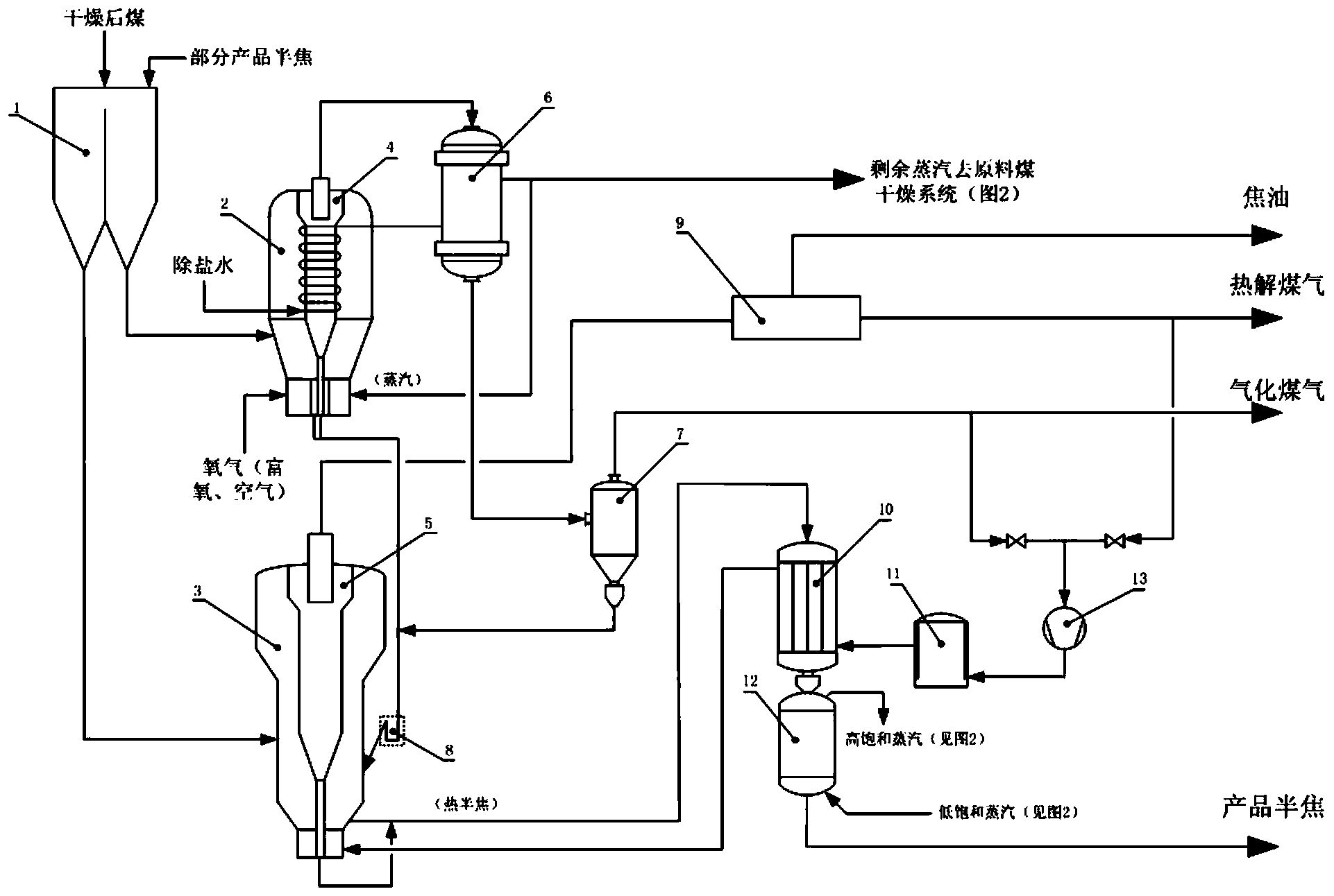
[0021] It includes a composite coal bunker, a combined gasifier and a combined pyrolysis furnace. The feed port of the type gasifier is connected, and the other discharge port is connected with the feed port of the combined pyrolysis furnace;

[0022] The operation mode of the combined gasifier is in the form of a fluidized bed, and there is a built-in separator in the gasifier in the form of multi-inlet and cyclone separation. The central axis of the built-in separator in the gasifier is in line with the The central axis of the gasifier coincides, the top is flush with the top of the combined gasifier, and a hot gas outlet pipe is provided;

[0023] The hot gas outlet pipe is connected to the air inlet of the shell-and-tube waste heat boiler, the gas outlet of the shell-and-tube waste heat boiler is connected to the air inlet of the hard tube dust collector, and t...

specific Embodiment

[0032] like figure 1 As shown, the treated raw coal and the semi-coke produced by the system are sent to the lower part of the combined gasifier 2 through the composite coal bunker 1; The co-action of the combined gasifier generates heat and performs partial gasification; the semi-coke produced by the combined gasifier 2 and the semi-coke powder separated by the built-in separator 4 of the gasifier pass through the semi-coke at the bottom of the combined gasifier 2 respectively. The outlet and the separated ash outlet of the separator are sent to the hot semi-coke return valve 8 connected with the combined pyrolysis furnace 3, and then sent into the combined pyrolysis furnace 3. At the same time, the gasification hot coal gas produced in the combined gasifier 2 enters the hot gas inlet of the shell-and-tube waste heat boiler 6 through the outlet pipe of the built-in separator 4 of the gasifier; After exchanging heat with desalted water in 6, the temperature is lowered to abou...


PUM


Abstract

The invention discloses a combined coal pyrolysis gasification system which comprises a raw material coal drying system, a composite coal bin, a combined gasification furnace and a combined pyrolysis furnace, wherein the combined gasification furnace is arranged at the upper part of the combined pyrolysis furnace; the combined gasification furnace operates in a fluidized bed form, and a gasification furnace built-in separator is arranged inside the combined gasification furnace; a hot gas outlet pipe of the gasification furnace built-in separator is connected with a gas inlet of a tube shell type waste heat boiler; the combined pyrolysis furnace operates in a fluidized bed form, and a pyrolysis furnace built-in separator is arranged inside the combined pyrolysis furnace; a raw gas outlet pipe of the pyrolysis furnace built-in separator is connected with a gas inlet of a pyrolysis gas purification system; a discharge port of the combined gasification furnace and a discharge port of the gasification furnace built-in separator are connected with a hot semicoke inlet of the combined pyrolysis furnace through hot semicoke return valves. The combined coal pyrolysis gasification system realizes graded utilization of coal, is favorable for saving energy and reducing emission, and can increase economic benefits of an enterprise.

Description

technical field [0001] The invention relates to a coal pyrolysis device and a gasification device, in particular to a combined briquette coal pyrolysis gasification system. Background technique [0002] There are a large number of low-metamorphic coal types distributed in northern Shaanxi, Inner Mongolia, Xinjiang, and Yunnan, such as lignite and long-flame coal. This type of coal has large resource reserves, shallow buried beds, good coal quality, low mining cost, and good chemical activity. , high volatile content, high calorific value, and non-cohesive properties are conducive to the extraction of tar and chemical fuel gas through pyrolysis. However, most coal pyrolysis devices in my country currently use lump coal, and a large amount of pulverized coal produced during the mining process cannot be utilized, and the current low-temperature dry distillation process will produce a large amount of raw coal gas that cannot be further utilized, so the effective components of co...

Claims


Application Information

Patent Timeline
Patent Type & Authority Applications(China)
IPC IPC(8): C10J3/60C10J3/56C10J3/84
CPCY02P20/10Y02P20/129
Inventor 许振华王五一祝龙于莉
Owner BEIJING LANTIAN LIYUAN SCI & TECH
Why Eureka
Try Eureka