Mounting correction tool for protection corner angle of frame column and manufacturing method thereof

A frame column and corner technology, which is applied in infrastructure engineering, architecture, building construction, etc., can solve the problems of inconvenient installation and correction method of frame column edge guard angle steel, difficult to ensure installation quality, time-consuming and troublesome, etc., to reduce operation. Procedure and labor intensity, ensure appearance quality, and correct the effect of intuitive operation

Active Publication Date: 2014-08-06
MCC5 GROUP CORP SHANGHAI
View PDF5 Cites 8 Cited by
  • Summary
  • Abstract
  • Description
  • Claims
  • Application Information

AI Technical Summary

Problems solved by technology

When installing the frame column edge protection angle steel, the general installation and correction method is adopted, that is, the size of the steel frame column is adjusted by artificially pulling the hard top. This method is not easy to operate, laborious, time-consuming and troublesome, and it is not easy to ensure the installation quality.
[0003] Therefore, there are above-mentioned inconveniences and problems in the known frame column edge protection angle steel installation correction method

Method used


Image

  • Mounting correction tool for protection corner angle of frame column and manufacturing method thereof
  • Mounting correction tool for protection corner angle of frame column and manufacturing method thereof
  • Mounting correction tool for protection corner angle of frame column and manufacturing method thereof

Examples


Embodiment Construction

[0032] The present invention will be further described below in conjunction with embodiment and accompanying drawing.

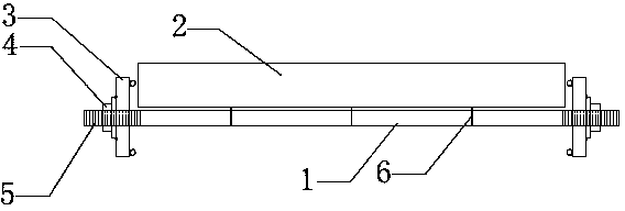
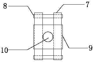
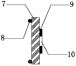
[0033] see now Figure 1 ~ Figure 3 , figure 1 It is a structural schematic diagram of installing a correction tool for the frame column edge protection angle steel of the present invention, figure 2 for figure 1 Enlarged front view of middle clip, image 3 for figure 2 side view. As shown in the figure, the screw rod 1 is a screw rod made of a round steel with a diameter of 14mm, and its length is 200mm longer than the section size of the installed frame column. The two ends of the screw rod are provided with threads and are equipped with fixing nuts 4, wherein There are several small holes that allow iron nails 6 to pass through the internal drill;

[0034] The length of the wooden side 2 is 5mm longer than the installed frame column section size, and it is connected and fixed with the screw rod 1 through the aperture of the screw rod 1 passed by th...


PUM

PropertyMeasurementUnit
diameteraaaaaaaaaa

Abstract

The invention relates to a mounting correction tool for a protection corner angle of a frame column. The tool comprises a screw rod (1), a square pillar (2) and two clamping pieces (3). The tool is characterized in that the screw rod (1) is a screw rod with the diameter of 12 to 16mm, the screw rod is made of round steel, the length of the screw rod is 200mm longer than that of the sectional dimension of the mounted frame column, threads which are formed in both ends of the screw rod are matched with fixing nuts (4), and a plurality of small holes for allowing iron nails (6) to pass through are drilled in the middle part; the length of the square pillar (2) is 5mm longer than that of the sectional dimension of the mounted frame column, and the small holes of the screw rod (1),through which the iron nails (6) pass, are connected and fixed with the screw rod (1); the clamping pieces (3) comprise two pairs of parallel steel bars (7,8) which are mutually vertical to form a well-shaped fixing weld to be welded and fixed with a steel plate (9), and a through hole (10) is formed in the center of the steel plate; the two clamping pieces (3) are arranged at both ends of the screw rod (1) in a sleeving manner and are screwed tightly and fixed by the nuts (4).

Description

technical field [0001] The invention relates to a correction tool, in particular to a correction tool for installing and correcting angle steel for frame column edge protection and a manufacturing method thereof. Background technique [0002] In the construction of construction projects, large-scale long-line elevated platform equipment foundations are often encountered, which are reinforced concrete frame structures. Since transport vehicles often pass by the reinforced concrete frame structure, in order to protect the frame column edges from vehicle collision damage, it is necessary to add edge protection angle steel to the four corners of the elevated platform frame column. When installing the frame column edge protection angle steel, the general installation and correction method is adopted, that is, the size of the steel frame column is adjusted by artificially pulling the hard top. This method is not easy to operate, laborious, time-consuming and troublesome, and it is...

Claims


Application Information

Patent Timeline
Patent Type & Authority Applications(China)
IPC IPC(8): E02D27/44E04G21/18B23P15/00
Inventor 邱战武
Owner MCC5 GROUP CORP SHANGHAI
Why Eureka
Try Eureka