Pneumatic magnetic energy storage needleless syringe

A needle-free syringe and magnetic technology, applied in the direction of syringes, hypodermic injection devices, infusion sets, etc., can solve the problems of poor manufacturing process, low cost, high cost, etc., and achieve excellent manufacturing process, good use performance, and shortened space. The effect of the itinerary

Inactive Publication Date: 2014-08-13
ZHANGJIAGANG INST OF IND TECH SOOCHOW UNIV
View PDF11 Cites 6 Cited by
  • Summary
  • Abstract
  • Description
  • Claims
  • Application Information

AI Technical Summary

Problems solved by technology

[0006] However, the current needle-free syringes driven by compressed air mainly have the following disadvantages: 1. The structure is extremely complex, the manufacturing precision is extremely high, and the cost is high; 2. In order to To seal the gas, the seal between the cylinder piston and the cylinder is generally sealed by a sealing ring, or a dynamic seal with a very small gap.
The cost of the former sealing method is lower, but the friction coefficient of the piston will change every time during the process of the piston from static friction to dynamic friction, and the range of change is generally about 20%, which causes the impact force of the cylinder piston to be unstable every time. The injection depth varies from deep to shallow; the latter sealing method, the cooperation between the piston and the inner hole of the cylinder is extremely precise, which generally needs to be achieved by the matching research process, not only the manufacturing process is not good, but also foreign matter such as fine dust is easy to enter , resulting in malfunction of the syringe

Method used


Image

  • Pneumatic magnetic energy storage needleless syringe
  • Pneumatic magnetic energy storage needleless syringe
  • Pneumatic magnetic energy storage needleless syringe

Examples


Embodiment 1

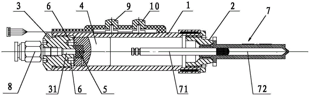
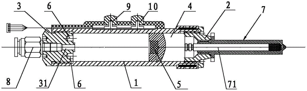
[0030] see figure 1 , figure 2 The shown needle-free syringe includes a cylinder 1 with an inner cavity, a front end cover 2 fixed on the front end of the cylinder 1 , a rear end cover 3 fixed on the rear end of the cylinder 1 , a needleless needle mounted on the front end cover 2 . The ampoule assembly 7, the impact member 4 provided in the inner chamber of the cylinder 1 movably in the forward and backward direction, and the gas source device (not shown in the figure) for providing compressed gas.

[0031] see figure 1 , figure 2 As shown, the rear end cover 3 is fixedly provided with a magnet 6 that can magnetically attract the impact member 4, and the rear end cover 3 is also provided with an air flow channel 31 communicating with the inner cavity of the cylinder 1. The rear end cover 3 of the impact member 4 A groove is provided on the part, and a seal 5 that can block the mouth of the airflow passage 31 is fixed in the groove, and the seal 5 can be a rubber ...

Embodiment 2

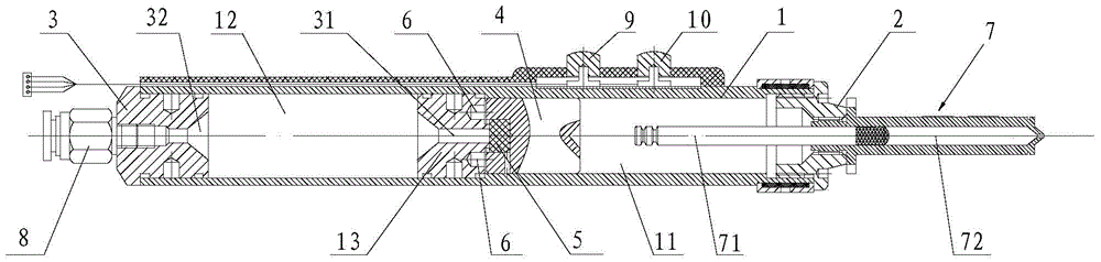
[0039] see image 3 As shown, the difference between this embodiment and Embodiment 1 lies in the setting of the gas storage chamber. In this embodiment, a fixed block 13 is also provided in the inner cavity of the cylinder 1, and the fixed block 13 divides the inner cavity of the cylinder 1 into a first chamber 11 and a second chamber 12 which are independent of each other along the front and rear directions. , the impact member 4 is located in the first chamber 11, the magnet 6 is fixed on the front part of the fixed block 13, and the fixed block 13 is provided with an airflow channel 31 communicating with the first chamber 11 and the second chamber 12, and the rear end cover 3 is provided with an air inlet 32, the air inlet pipe on the air source device is connected to the rear end cover through a joint, and the lumen of the air inlet pipe, the air inlet 32, the second chamber 12 and the air flow channel 31 are formed A storage chamber for storing compressed gas. This c...


PUM


Abstract

The invention discloses a pneumatic magnetic energy storage needleless syringe. The syringe comprises a cylinder barrel with an inner cavity, a front end cover fixedly arranged at the front end of the cylinder barrel, a rear end cover fixedly arranged at the rear end of the cylinder barrel, a needleless ampoule assembly arranged on the front end cover and an impact part movably arranged in the inner cavity of the cylinder barrel along the front and back direction; the rear end cover is fixedly provided with a magnet capable of magnetically attracting the impact part; the rear end cover is also provided with an air flow passage communicated with the inner cavity of the cylinder barrel; a seal part capable of plugging the air flow passage is fixedly arranged at the rear part of the impact part; the needleless syringe also comprises an air source device for charging compressed air into the air flow passage; the needleless ampoule assembly at least comprises a piston rod capable of moving front and back. The compressed air is charged into the air flow passage by the air source device, and when the air pressure value in the air flow passage achieves a certain value, the impact part overcomes the magnetic force of the magnet to forwards impact to realize the injection process. The needleless syringe is simple in structure and excellent in manufacturing process and has well use performances.

Description

[0001] technical field [0002] The invention relates to a pneumatic magnetic energy storage type needle-free injector. [0003] Background technique [0004] Needle-free injection technology is to inject liquid medicine directly into the body tissues in the form of ultra-fine, high-speed, and straight-line high-pressure jets without the use of needles, which solves a series of problems caused by traditional injections caused by needles piercing the body. , such as: pain, bleeding, infection, tissue damage, psychological stress of patients, etc.; at the same time, the distribution of drugs injected without needles in the tissue is more diffuse, which is conducive to the absorption of drugs, and the skin is not easy to harden after long-term injection. Therefore, needle-free injection technology has broad application prospects, especially for children's vaccination and diabetic patients. [0005] In the prior art, some needle-free injectors are often driven by air pressur...

Claims


Application Information

Patent Timeline
Patent Type & Authority Applications(China)
IPC IPC(8): A61M5/307A61M5/31
Inventor 王明娣孙万平窦云霞王传洋
Owner ZHANGJIAGANG INST OF IND TECH SOOCHOW UNIV
Why Eureka
Try Eureka