Lightweight electric vehicle body skeleton

A lightweight technology for electric vehicles, applied to vehicle components, superstructures, superstructure subassemblies, etc., can solve problems such as low energy storage density of power batteries, low effective load efficiency, and large battery pack volume, and achieve consensus The advantages of high performance and light weight, guaranteed forming quality and connection reliability, and easy processing

Inactive Publication Date: 2014-08-13
INST OF DONGGUAN SUN YAT SEN UNIV +1
View PDF5 Cites 22 Cited by
  • Summary
  • Abstract
  • Description
  • Claims
  • Application Information

AI Technical Summary

Problems solved by technology

At present, the difficulties faced by the development of the electric vehicle industry are as follows: (1) The energy storage density of the power battery is not high, resulting in a large volume and high quality of the battery pack; (2) The effective load efficiency is low, only 1 / 4 to 1 / 5, and most Energy consumption in moving non-payloads

Method used


Image

  • Lightweight electric vehicle body skeleton
  • Lightweight electric vehicle body skeleton
  • Lightweight electric vehicle body skeleton

Examples


Embodiment 1

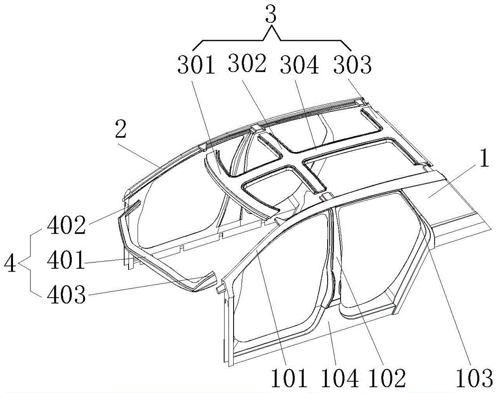
[0040] Such as figure 1 Shown is a lightweight electric vehicle body frame, the body frame is made of carbon fiber material, and is designed and produced using the design method of "four blocks and eight small pieces".

[0041] The four blocks are the left body frame 1, the right body frame 2, the roof 3 and the front glass bracket 4. The left body frame 1 and the right body frame 2 pass through the roof 3 and the front glass bracket 4 respectively. Gluing and bolt fastening are assembled to obtain a space-cage tubular body frame.

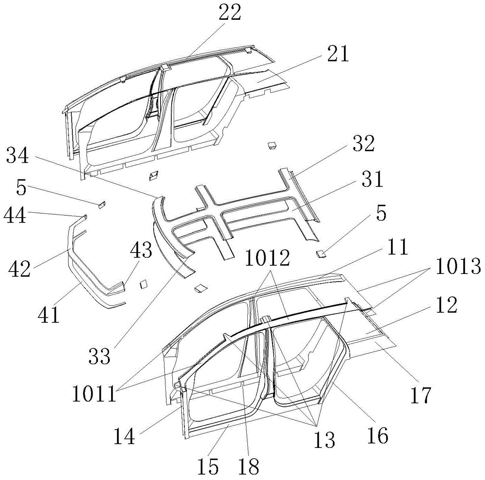
[0042] The eight small pieces are obtained by dividing each of the four major blocks into two pieces, the inner and outer pieces, with the edge area as the parting surface, as shown in figure 2 As shown, the left body frame 1 is divided into a left inner body piece 11 and a left outer body piece 12, the right side body frame 2 is divided into a right inner body piece 21 and a right outer body piece 22, and the roof 3 is divided into The inner ro...

Embodiment 2

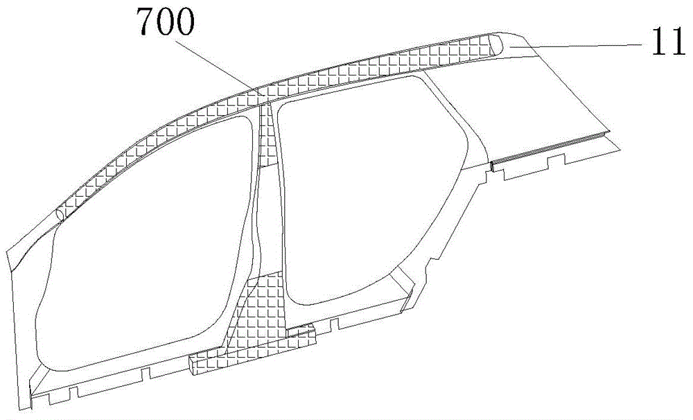
[0057] Such as image 3 As shown, on the basis of the first embodiment, this embodiment adopts the method of thickening the layup 700 to require higher load-bearing positions, such as the "A" pillar 101, the "B" pillar 102 and the bottom "mountain" character structure 104 , for local reinforcement. The feature of this scheme is that in the process of product layup, the local reinforcement area is reasonably selected and designed, and in the process of carbon fiber layup, the purpose of increasing the overall strength of the area is achieved by increasing the number of carbon fiber cloth layers. The advantage of this scheme is that detailed design is carried out in the production process, the operation is simple and the enhancement effect is obvious.

Embodiment 3

[0059] Such as Figure 4 As shown, on the basis of the first embodiment, this embodiment adopts the method of adding a partition 800 to a higher load-bearing position, such as the "A" pillar 101, the "B" pillar 102 and the bottom "mountain" character structure 104, Do local reinforcement. The feature of this solution is that after the product layering is completed, between the inner and outer slices of the hollow area, reinforcement is carried out by arranging partitions 800 to play the role of internal reinforcement. The material of the partition 800 can be hard materials such as carbon fiber, and the partition can be in the form of interlaced vertical and horizontal plates. This solution can greatly improve the overall rigidity, strength and crashworthiness of the hollow structure, but requires additional partition processing and staggered design.


PUM


Abstract

The invention relates to the technical field of electric vehicles, in particular to a lightweight electric vehicle body skeleton, which comprises a left side body frame, a right side body frame, a roof and a front glass bracket which are all made of carbon fiber reinforced composite materials, wherein the left side body frame and the right side body frame are respectively assembled with the roof and the front glass bracket in a cementing manner and a bolt fastening manner to form a space cage-shaped tubular body skeleton, each of the four large blocks takes an edge combining area as a piece dividing line and is further divided into an inner piece and an outer piece, and the inner pieces and the outer pieces are connected at the edge combining areas in a cementing manner. The application form of composite materials to the vehicle body is improved from the past single sided board into a double sided tubular space structure, a passenger protecting area is designed into a space cage-shaped skeleton structure, the overall strength of the body skeleton is improved through utilizing the structure characteristics of tubular columns and topological spaces, in addition, the forming efficiency is also considered by adopting the four-large-block and eight-small-piece designing method, and the forming quality is also effectively ensured.

Description

technical field [0001] The invention relates to the technical field of electric vehicles, in particular to a lightweight electric vehicle body frame made of carbon fiber materials. Background technique [0002] Facing the dual pressure of energy crisis and environmental pollution, electric vehicles have become a hot spot for global development. At present, the difficulties faced by the development of the electric vehicle industry are as follows: (1) The energy storage density of the power battery is not high, resulting in a large volume and high quality of the battery pack; (2) The effective load efficiency is low, only 1 / 4 to 1 / 5, and most Energy is spent on moving non-payloads. Lightweight technology can increase the payload rate by reducing its own weight, thereby extending the driving range, especially when the current power battery cost is high and the energy storage level is insufficient, it is of great significance to promote the industrialization of electric vehicle...

Claims


Application Information

Patent Timeline
Patent Type & Authority Applications(China)
IPC IPC(8): B62D25/00
Inventor 宗志坚刘强林海峰龙飞永
Owner INST OF DONGGUAN SUN YAT SEN UNIV
Why Eureka
Try Eureka