
Oil and gas field drilling fluid sludge treatment method

A sludge treatment and drilling fluid technology, applied in the fields of sludge treatment, water/sludge/sewage treatment, mining wastewater treatment, etc., can solve the problem that the environmental protection measures of the sludge tank are difficult to maintain and protect, increase the cost of environmental protection treatment, and endanger the surrounding environment. and other problems, to achieve the effect of small footprint, high degree of automation and convenient transportation

Inactive Publication Date: 2015-08-19
中国石油天然气股份有限公司长庆油田分公司第二采气厂
View PDF2 Cites 0 Cited by
  • Summary
  • Abstract
  • Description
  • Claims
  • Application Information

AI Technical Summary

Problems solved by technology

[0009] 2. The sludge pond shall be protected by environmental protection measures;
[0010] 3. Drilling fluid needs to be transported to different places for environmental protection treatment
Since oil and gas drilling operations in oil fields have a certain period of time, it is difficult for the environmental protection measures of the sludge tank to maintain such a long-term protection, which will seriously endanger the surrounding environment from three aspects (gas, water, and land)
In particular, drilling fluid needs to be transported to different places for environmental protection treatment, which not only increases the cost of environmental protection treatment, but also brings environmental pollution along the way.

Method used


Image

  • Oil and gas field drilling fluid sludge treatment method

Examples


Embodiment Construction

[0048] Below in conjunction with accompanying drawing and embodiment describe in detail:

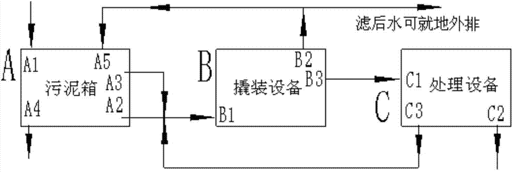
[0049] 1. System

[0050] 1. Overall

[0051] Such as figure 1 , this system includes skid-mounted equipment B (ZL201210145000.1) and processing equipment C (ZL 201310493396.3):

[0052] Set up with sludge tank A:

[0053] Sludge tank A, skid-mounted equipment B and treatment equipment C are connected in sequence;

[0054] The sludge tank A is a square box without a cover, 14m long, 3m wide, and 3.4m high; in the sludge tank A, there are drilling fluid inlet A1, drilling fluid sewage outlet A2, flushing water outlet A3, 1# The sludge outlet for cleaning and treatment (the treated sludge can be landfilled on site) A4 and the filtered water reuse inlet A5;

[0055] In the skid-mounted equipment B, there are drilling fluid sewage inlet B1, filtered water outlet (the filtered water can be directly discharged or used as reused clean water for cleaning 1# sludge) B2 and 2# sludge outlet B...


PUM


Abstract

The invention discloses a drilling fluid sludge treatment system for an oil-gas field and a method using the system, relating to the drilling fluid sludge treatment technology for the oil-gas field. The system comprises skid-mounted equipment (B), treatment equipment (C) and a sludge tank (A), wherein the sludge tank (A), the skid-mounted equipment (B) and the treatment equipment (C) are connected in sequence; a drilling fluid wastewater outlet (A2) and a flushing water outlet (A3) are respectively connected with a drilling fluid wastewater inlet (B1); a 2# sludge outlet (B3) is connected with a 2# sludge inlet (C1); a wastewater outlet (C3) for sludge dewatering is connected with the drilling fluid wastewater inlet (B1); a filtered water outlet (B2) is connected with a filtered water recycling inlet (A5). According to the system, the soil does not need to be dug on site for building the large sludge tank, and drilling fluid sludge can be timely treated on site and subjected to emission on standard and in-place landfill; the process is simple, the transportation is convenient, and the field assembly is quick; the area occupation is small, the automation level is high, and the system can move along with the transfer of the drilling work.

Description

technical field [0001] The invention relates to oil and gas field drilling fluid sludge treatment technology, in particular to an oil and gas field drilling fluid sludge treatment system and method thereof. Background technique [0002] In Cheng Zhonghe's invention patent "Oily Sludge Dehydration Treatment Equipment and Its Method" (application date: 2013-10-21, application number: 201310493396.3, publication date: 2014-01-08, publication number: CN103496837A) related to the application The section describes it like this: [0003] The combination of "this oily sludge dehydration treatment equipment" and "integrated skid-mounted equipment for oily sewage and sludge resource treatment" (see another invention patent of Cheng Zhonghe: ZL 2012 1 0145000.1) can treat oilfield drilling fluid sludge . " [0004] "Traditional drilling fluid sludge treatment is to temporarily place the sewage and sludge from drilling in an open-air sludge pool, and place thicker plastic with envir...

Claims


Application Information

Patent Timeline
Patent Type & Authority Patents(China)
IPC IPC(8): C02F11/00C02F103/10
Inventor 刘帮华解永刚胡均志王喜娟赵轩刚马连伟何彦君徐东赖燕程中和
Owner 中国石油天然气股份有限公司长庆油田分公司第二采气厂
Learn More