
Method of improving yarn surface structure in positive holding rotation mode

A surface structure and rotary technology, applied in the field of textile processing, can solve the problems of no essential improvement in the quality of knitted products, the inability to form dense structural connections, and the deterioration of the uniformity of the main body of the yarn, etc. Abrasion resistance and wide application range

Inactive Publication Date: 2014-08-13
WUHAN TEXTILE UNIV
View PDF18 Cites 31 Cited by
  • Summary
  • Abstract
  • Description
  • Claims
  • Application Information

AI Technical Summary

Problems solved by technology

[0007] It can be seen that the above-mentioned yarn hairiness control for the yarn use process such as winding, warping, knitting, etc., the common point of the existing methods is: false twisting or air blowing of the yarn under the condition of not actively holding the head end of the hairiness Wrapping, winding most of the hairiness protruding from the surface of the yarn in a loose form, and sticking to the yarn surface, the dense structural connection between the hairiness fiber and the yarn body cannot be formed, and the reduction of hairiness can only be achieved visually ;Aiming at the form of untwisting-twisting, in the process of attaching hairiness, the local twist of the yarn is dynamically transferred and redistributed, and the weak twist appears, which is easily stretched by the yarn tension and deteriorates the evenness of the main body of the yarn
More importantly, in the subsequent process, as the yarn is rubbed by the machine parts, the fibers that are loosely wound and attached to the surface of the yarn are easy to protrude out of the surface of the yarn again to form hairiness, which is harmful to the yarn in the subsequent process. The processing of the process and the quality of the final product (especially the quality of knitted products) have not improved substantially

Method used


Image

  • Method of improving yarn surface structure in positive holding rotation mode
  • Method of improving yarn surface structure in positive holding rotation mode
  • Method of improving yarn surface structure in positive holding rotation mode

Examples


Embodiment 1

[0020] Example 1: In the process of ring spinning, improving the smoothness of ring spinning

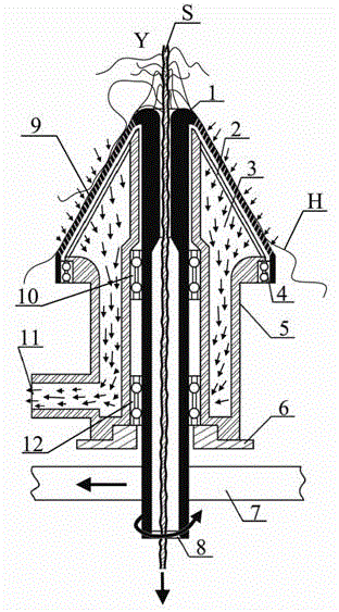
[0021] On the ring spinning frame, the Houka fixing device is used to fix and install the holding and rotating yarn hairiness reducing device between the front roller jaw and the yarn guide hook of the ring spinning frame through the air channel base 5, and the holding and rotating type lowers the yarn hairiness. The front center positioning yarn guide hook is set between the yarn hairiness device and the front roller nip, the rear center positioning yarn guide hook is set between the holding rotary yarn hairiness reducing device and the yarn guide hook, and the speed regulating motor is installed on the ring spindle The headstock of the spinning frame is connected with the power cord of the ring spinning frame headstock to obtain energy to drive the transmission belt 7 to move, and the transmission belt 7 is tightly pressed against the rotation shaft of the rotator 1 through the belt...

Embodiment 2

[0022] Example 2: During the winding process, improving the smoothness and density of the ring-spun yarn surface structure

[0023] On the automatic winding machine, the Houka fixing device is used to fix and install the holding and rotating yarn hairiness reducing device between the electronic yarn clearer and the waxing device of the automatic winding machine through the air channel base 5, and the holding and rotating type The front center positioning yarn guide hook is set between the yarn hairiness reducing device and the electronic yarn clearer, the rear center positioning yarn guide hook is set between the rotary yarn hairiness reducing device and the waxing device, and the speed regulating motor is installed on the whole On the side wall of the control box corresponding to each trough on the automatic winder, energy is obtained by connecting with the power line in the control box to drive the transmission belt 7 to move, and the transmission belt 7 is tightly pressed ag...

Embodiment 3

[0024] Example 3: In the warping process, improving the smoothness and density of the yarn surface structure

[0025]On the warping machine, the Houka fixing device is used to fix and install the holding and rotating type yarn hairiness reducing device on the row of yarn guide rods at the yarn output end of the warping machine creel through the air channel base 5, and the holding and rotating type The yarn hairiness reducing device is located between the yarn guide rod and the retractable buckle, and the rotary yarn hairiness reduction device and the yarn guide on the yarn guide rod are provided with a front center positioning yarn guide hook, and the rotary yarn hairiness reduction device is installed A rear center positioning yarn guide hook is set between the retractable buckle, and the speed-regulating motor is installed on the main support rod of the creel, and the energy obtained by an external power supply drives the transmission belt 7 to move, and the transmission belt...


PUM

PropertyMeasurementUnit
Diameteraaaaaaaaaa

Abstract

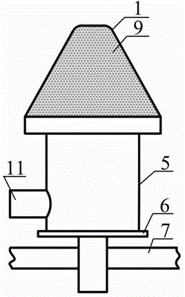
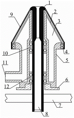
The invention relates to a method of improving a yarn surface structure in a positive holding rotation mode and belongs to the technical field of textile processing. According to the method, a front central positioning yarn guide hook, a holding rotation type yarn hairiness reducing device and a rear central positioning yarn guide hook are arranged on the operation path of each yarn in sequence, wherein each yarn enters the holding rotation type yarn hairiness reducing device through the front central positioning yarn guide hook; the trunk of the yarn enters the center of a yarn channel and keeps a tensioning straightening state, the surface hairiness of the yarn is subjected to a negative pressure air draft effect, the hairiness is absorbed on the outer surface of a conical housing and synchronously rotates along with the conical housing, and meanwhile, at the inlet of the yarn channel, the hairiness continues tightly winding the operating yarn trunk, and the smooth densifying treatment is realized on the yarn surface structure. The method is wide in applicable range and can be used for processing various yarns; the holding rotation type yarn hairiness reducing device is reasonable in structure and convenient to operate.

Description

technical field [0001] The invention relates to a method for actively gripping and rotating the yarn surface to improve the structure, and belongs to the technical field of textile processing. technical background [0002] Hairiness is one of the important indicators to measure the quality of yarn. Yarn hairiness not only affects the production efficiency of weaving, knitting and other post-processes, but also affects the appearance quality of the final product. Especially today, when high-speed shuttleless looms are widely used, reducing yarn hairiness is of great significance. [0003] Yarn hairiness occurs in the spinning process. The mechanism is that after the end of the fiber transferred from inside and outside is exposed to the yarn body, it breaks away from the grip of the jaws and cannot re-enter or wrap around the main body of the yarn body, forming hairiness. The hairiness increases in the winding and warping process. The root cause is that there are many hairine...

Claims


Application Information

Patent Timeline
IPC IPC(8): D01H5/28D01H13/00
Inventor 夏治刚徐卫林凌良仲曹根阳
Owner WUHAN TEXTILE UNIV
Learn More