Wind power generation network camera monitoring and communication transmitting antenna tower

A network camera and forwarding antenna technology, which is applied in the field of wind power generation network camera monitoring and communication forwarding antenna towers, can solve the problems of reducing the rotation speed, wasting wind resources, and high cost, extending the wind outlet track and vortex angle, and improving power generation. Ability, the effect of overcoming the dead angle of rotation

Active Publication Date: 2014-08-13
杭州爱纬斯电子有限公司
View PDF6 Cites 16 Cited by
  • Summary
  • Abstract
  • Description
  • Claims
  • Application Information

AI Technical Summary

Problems solved by technology

[0002] The power supply of the network camera monitoring and communication forwarding antenna tower in the prior art is supplied by the mains, and the battery is used as a short-term backup power supply. Therefore, it lacks the long-term anti-war and disaster-resisting ability that can be triggered immediately. Once an irresistible natural disaster or war breaks out, When the power supply system is interrupted or the mains supply is paralyzed, city monitoring and communication will be unsustainable; therefore, it is very necessary and energy-saving to design a wind power network camera monitoring and communication forwarding antenna tower powered by advanced wind power
[0003] The current vertical axis wind power generation products generally have defects such as insufficient output power, high cost, and insufficient safety and reliability due to ground conditions, difficulty in making the wind rotor larger and safety facto

Method used


Image

  • Wind power generation network camera monitoring and communication transmitting antenna tower
  • Wind power generation network camera monitoring and communication transmitting antenna tower
  • Wind power generation network camera monitoring and communication transmitting antenna tower

Examples


Example Embodiment

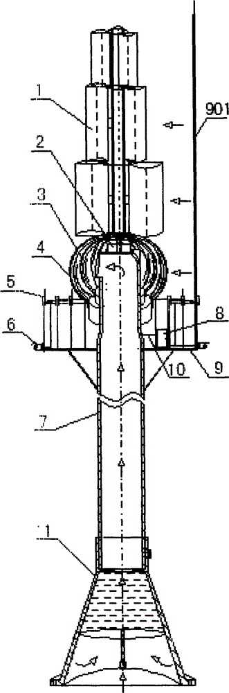
[0032] Example: attached figure 1 It is a schematic diagram of the structural principle of a wind power generation network camera monitoring and communication forwarding antenna tower; as a preference, in the figure: 1. The first wind rotor, 2. The generator, 3. The third wind rotor, 4. The second wind rotor, 5. Several wireless communication transponders, 6. Several network cameras, 7. Tower columns, 8. Control boxes, 9. Towers, 10. Wires, 11. Tower bases; among them, the wind bucket in the first wind wheel 1 An elongated frame 117 is set between the metal pipe 116 and is a square metal frame, which is respectively fixed with the wind bucket and the metal pipe 116 on both sides as a support, and the middle of the elongated frame is for airflow to pass through to reduce resistance.

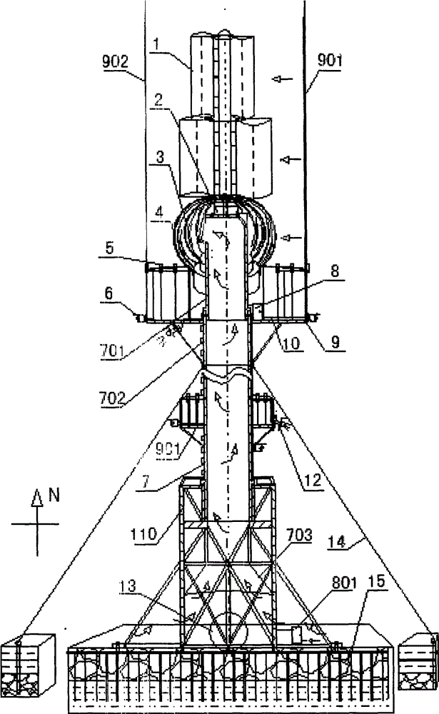
[0033] Example: attached figure 2 It is a schematic diagram of the structural principle of a large-scale wind power generation network camera monitoring and communication forwarding antenna towe...


PUM


Abstract

The invention discloses a wind power generation network camera monitoring and communication transmitting antenna tower and belongs to the technical field of wind power energy. The inner ventilation wind pulling force is utilized to enable ground air flow to pass through the inside of a tower seat, a tower column and a tower column head to be discharged from an air outlet to push a turbo type spherical air wheel and a wind scoop capable of being opened and closed automatically in the wind direction to rotate to guide a natural air source to push the air wheel to rotate from the upper portion, the middle portion, the lower portion and the inside, and the power generation capability is improved. The wind scoop is closed automatically in the wind direction, and wind direction resistance is reduced. A wind fixing ball enables the ground air flow to rise in the spiral tornado type from the surface of the wind fixing ball to generate spiral rotating torque. A wind power generator is utilized as a main power supply, a mains supply is utilized as a reserve power supply, the network camera monitoring and communication transmitting anti-war anti-disaster capability is improved, safety operation of urban monitoring and communication transmitting is ensured, and the tower saves energy and is environmentally friendly.

Description

technical field [0001] The invention relates to a network camera monitoring and communication forwarding antenna tower for wind power generation, and belongs to the technical field of network camera monitoring and communication forwarding antenna towers powered by clean energy for wind power generation. Background technique [0002] The power supply of the network camera monitoring and communication forwarding antenna tower in the prior art is supplied by the mains, and the battery is used as a short-term backup power supply. Therefore, it lacks the long-term anti-war and disaster-resisting ability that can be triggered immediately. Once an irresistible natural disaster or war breaks out, When the power supply system is interrupted or the mains supply is paralyzed, city monitoring and communication will be unsustainable; therefore, it is very necessary and energy-saving to design a wind power network camera monitoring and communication forwarding antenna tower powered by adva...

Claims


Application Information

Patent Timeline
IPC IPC(8): F03D9/00F03D3/02F03D3/06F03D11/00F03D7/06
CPCY02E10/74
Inventor 陈国祥
Owner 杭州爱纬斯电子有限公司
Why Eureka
Try Eureka