
Two-stage compression air conditioning system with defrosting function

A technology for compressing air conditioners and two-stage compressors, which is applied to compressors with reversible cycles, compressors, lighting and heating equipment, etc. It can solve the problems of prolonging defrosting time, slow defrosting speed, and refrigerant entry, etc., to achieve Guaranteed comfort, fast heat release, and sufficient heat storage

Active Publication Date: 2014-08-13
GREE ELECTRICAL APPLIANCE SHIJIAZHUANG +1
View PDF7 Cites 18 Cited by
  • Summary
  • Abstract
  • Description
  • Claims
  • Application Information

AI Technical Summary

Problems solved by technology

Although this defrosting method can solve the above-mentioned problems existing in the traditional defrosting method, since the defrosting method uses the heat generated by the compressor to store heat, the phase change temperature point of the phase change heat storage material used will inevitably be If the temperature is lower, the heat absorption and heat release speed of the heat storage material will be slower, so that the defrosting speed will be slower, and the defrosting time will be prolonged, which will also affect the heating effect and comfort
Especially for the two-stage compression air conditioning system with defrosting function, when heating, due to the existence of the flash evaporator, the refrigerant must be subcooled again when it flows through the flash evaporator, that is, the refrigerant flowing into the outdoor heat exchanger must be at Lower temperatures than single-stage compression, so frosting will be more severe and frequent, so defrosting will be slower
Moreover, defrosting when the accumulator has insufficient heat storage will cause a large amount of refrigerant that cannot be evaporated to enter the compressor, thereby posing a fatal threat to the reliability of the compressor.

Method used


Image

  • Two-stage compression air conditioning system with defrosting function
  • Two-stage compression air conditioning system with defrosting function
  • Two-stage compression air conditioning system with defrosting function

Examples


Embodiment 1

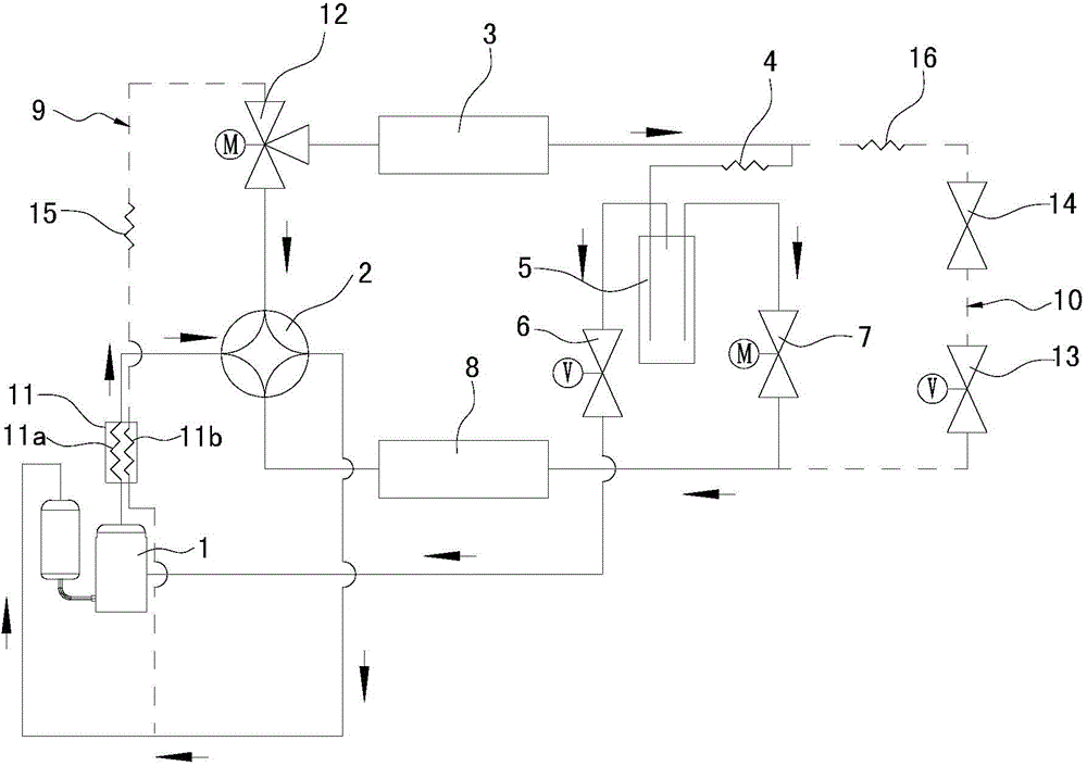
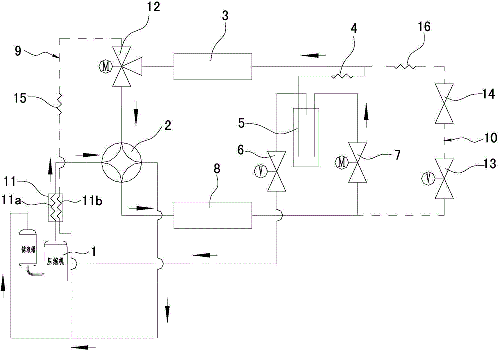
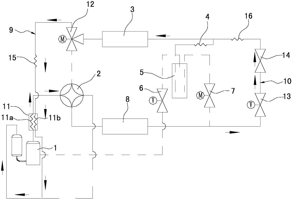
[0029] Such as Figure 1~3As shown, the two-stage compression air-conditioning system with defrosting function in this embodiment is the same as the existing two-stage compression air-conditioning system with defrosting function: both include a two-stage compressor 1 and a four-way reversing valve 2 , an outdoor heat exchanger 3, a first throttling device 4, a flash evaporator 5, a second throttling device 7 and an indoor heat exchanger 8, wherein the exhaust port and the suction port of the two-stage compressor 1 pass through the The four-way reversing valve 2 is connected to the first end of the outdoor heat exchanger 3 and the first end of the indoor heat exchanger 8, and the second end of the outdoor heat exchanger 3 passes through the first throttling device 4 is connected to the first interface of the flash evaporator 5, the second interface of the flash evaporator 5 is connected to the second end of the indoor heat exchanger 8 through the second throttling device 7, and...

Embodiment 2

[0040] Figure 4 Shown is a schematic diagram of a two-stage compression air-conditioning system with defrosting function in Embodiment 2 of the present invention. The difference from Embodiment 1 is that one end of the second bypass pipeline 10 is connected to the pipeline between the second end of the outdoor heat exchanger 3 and the first throttling device 4 , and the other end is connected to On the pipeline between the flasher 5 and the second throttling device 7 . During defrosting, after the refrigerant flows out of the indoor heat exchanger 8, it passes through the second throttling device 7 and enters the second bypass pipeline 10. At this time, the opening degree of the second throttling device 7 is the largest, and there is only a slight throttling of the refrigerant. flow effect.

Embodiment 3

[0042] Figure 5 Shown is a schematic diagram of a two-stage compression air-conditioning system with defrosting function in Embodiment 2 of the present invention. The difference from Embodiment 1 is that the three-way valve 12 is arranged behind the four-way reversing valve 2, that is, the first port of the three-way valve 12 is connected to the four-way reversing valve 2 through a refrigerant pipe, and the The second port of the three-way valve 12 is connected to the suction port of the two-stage compressor 1 through a refrigerant pipe, and the third port of the three-way valve 12 is connected to one end of the first bypass pipe 9 through a refrigerant pipe. The other end of the first bypass pipeline 9 is connected to the pipeline between the second interface of the three-way valve 12 and the suction port of the two-stage compressor 1 .


PUM


Abstract

The invention relates to a two-stage compression air conditioning system with a defrosting function. The two-stage compression air conditioning system with the defrosting function comprises a two-stage compressor, a four-way reversing valve, an outdoor heat exchanger, a first throttling device, a flash evaporator, a second throttling device and an indoor heat exchanger, and also comprises a first bypass pipeline, a heat accumulator and a control valve, wherein the first bypass pipeline is connected between the first end of the outdoor heat exchanger and an air suction opening of the two-stage compressor, the heat accumulator is provided with a first heat exchange pipe and a second heat exchange pipe, the first heat exchange pipe is connected in series onto a pipeline arranged between an exhaust opening of the two-stage compressor and the first end of the indoor heat exchanger, the second heat exchange pipe is connected in series onto the first bypass pipeline, and the control valve is used for controlling coolants to flow back to the air suction opening of the two-stage compressor through the first bypass pipeline or a pipeline arranged between the first end of the outdoor heat exchanger and the air suction opening of the two-stage compressor. The two-stage compression air conditioning system with the defrosting function has the advantages that the defrosting speed is high, the defrosting time is short, the use comfort of users can be ensured, and in addition, the adverse influence on the compressor caused during the defrosting can be avoided.

Description

technical field [0001] The invention relates to the field of air conditioning, in particular to a two-stage compression air conditioning system with a defrosting function. Background technique [0002] During the operation of the air conditioner in the cold winter season, the temperature of the outdoor heat exchanger is lower than the ambient temperature. If the outdoor ambient temperature is lower than 7°C, the surface temperature of the outdoor heat exchanger may be lower than 0°C; if the outdoor ambient humidity is high enough at the same time, this will cause frost or even ice on the outdoor heat exchanger, which will seriously hinder The heat exchange of the outdoor heat exchanger causes the heating performance of the air conditioning system to rapidly and greatly attenuate, which significantly affects the heating effect of the air conditioner, and even causes the air conditioner compressor to fail. For this reason, it is necessary to defrost the outdoor heat exchanger...

Claims


Application Information

Patent Timeline
IPC IPC(8): F25B13/00F25B47/00F25B41/04F25B41/06F25B41/20F25B41/31F25B41/37
Inventor 李大伟熊军粱志滔罗永前
Owner GREE ELECTRICAL APPLIANCE SHIJIAZHUANG
Learn More