Mixed fit device for biomass fuel, paper sludge and coals

A biomass fuel and papermaking sludge technology, applied in the direction of fuel supply, combustion method, combustion type, etc., can solve the problems of complex equipment composition, large coal treatment system, complex equipment installation, etc., and achieve the purpose of inhibiting ash deposition, corrosion, and The effect of low calorific value and good burnout characteristics

Active Publication Date: 2013-03-20
CHINA LIGHT IND WUHAN DESIGN ENG CO LTD
View PDF8 Cites 6 Cited by
  • Summary
  • Abstract
  • Description
  • Claims
  • Application Information

AI Technical Summary

Problems solved by technology

[0008] 1. The equipment composition is relatively complex, the initial investment is relatively large, and the equipment installation is relatively complicated; the coal treatment system in front of the furnace is relatively large; 2. The coal bunker is very large
High energy consumption

Method used


Image

  • Mixed fit device for biomass fuel, paper sludge and coals
  • Mixed fit device for biomass fuel, paper sludge and coals

Examples


Embodiment 1

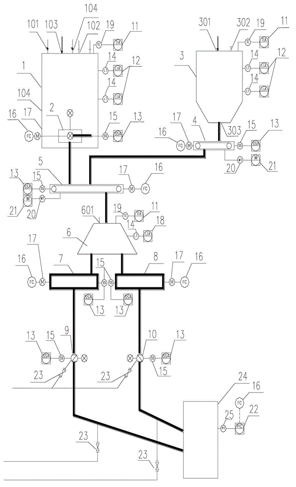
[0028] Such as figure 1 as shown,

[0029] A biomass fuel, papermaking sludge and coal mixing device, including a biomass material bin 1, a biomass bin screw conveyor 2, a coal bin 3, a frequency conversion coal screw conveyor 4, a frequency conversion scraper conveyor 5, and a furnace mixing Device 6, the first screw distributor 7, the second screw distributor 8, the first screw feeder 9, the second screw feeder 10 and the boiler 24, the biomass in the biomass material bin 1 is conveyed by the screw of the biomass material bin The machine 2 is sent to the frequency conversion scraper conveyor 5, the coal in the coal bunker 3 is sent to the frequency conversion scraper conveyor 5 through the frequency conversion coal screw conveyor 4, and the output end of the frequency conversion scraper conveyor 5 passes through the coal sliding pipe and the mixing device in front of the furnace 6 is connected to the input end, and the output end of the mixing device 6 in front of the furna...

Embodiment 2

[0036]Biomass silo 1 is located on the third floor (15-20 meters high), and the feed port of biomass silo 1 is connected to the feed slide pipe to connect with the feeding equipment; the fire hose is connected to the biomass through the fire outlet of the silo Bin 1; the inspection port is set at the manhole 104, and the top of the biomass bin 1 is provided with a bin exhaust port 102. The biomass bin screw conveyor 2 is connected to the outlet of the biomass bin 1 . The screw conveyor 2 of the biomass material bin is connected to the inlet of the variable frequency scraper conveyor 5 through a drop pipe; The outlet is connected to the inlet of the frequency conversion scraper conveyor 5 through the coal sliding pipe, the outlet of the frequency conversion scraper conveyor 5 is connected to the inlet of the mixing device 6 in front of the furnace through the discharge pipe, and the fire water pipe passes through the front of the mixing device 6 in front of the furnace The fir...


PUM


Abstract

The invention relates to a mixed fit device for biomass fuels, paper sludge and coals. Biomasses in a biomass bunker are conveyed to a variable frequency scraper conveyor through a biomass bunker screw conveyor; coals in a coal bunker are conveyed to the variable frequency scraper conveyor through a variable frequency coal screw conveyor; an output end of the variable frequency scraper conveyor is connected with an input end of a boiler-front mixing device through a coal drop pipe; and an output end of the boiler-front mixing device is connected with a boiler through a spiral distributor and a spiral feeder. In order to prevent the boiler-front blockage and tube pulling, the system is provided with a primary hot-air system. The fuel mixing technology adopts paper sludge (absolute dried), wood chips (absolute dried), and fuel coals distributed in normal operation (at most not exceed 20%); and the optimal operation effect is achieved through a PLC control system with high automation degree of the mixed fit of the biomass fuels, the paper sludge and the coals in front of a boiler. The sludge incineration technology has is superior, is combined with a sludge incineration power generation technology, and is a sludge treatment technology popular with paper making enterprises.

Description

Technical field [0001] The present invention involves high -temperature and high -pressure biomass boiler fuel mixing technology and control system fields. It specifically involves a biomass fuel, paper sludge and coal mixed coordination device.Suitable for the pulp and paper industry and small and medium -sized thermal power generation industries. Background technique [0002] Paper -making sludge ((Dry), Wood Chips (Dry), with at least coal -fired during normal operation. As the final disposal direction, although the sludge incineration disposal is slightly higher at one time, because it has the advantages of other craftsmanship that cannot be replaced, Especially in the reduction of sludge volume, hygiene, eventually out of the way, there are other processes that are unable to compare with the area of disposal.Some sewage treatment plants have been applied. Because sludge incineration has a great advantage, and the technology of using sludge incineration power generation, it i...

Claims


Application Information

Patent Timeline
Patent Type & Authority Applications(China)
IPC IPC(8): F23K3/00F23K5/00F23G7/00
Inventor 方习锋熊术娥杨华丽高敏梁斌康仙陵张劲松刘国栋胡佳琳段启坤沈威
Owner CHINA LIGHT IND WUHAN DESIGN ENG CO LTD
Why Eureka
Try Eureka