Sensor fault diagnosis system and diagnosis method based on signal and environment excitation

A technology of sensor failure and environmental excitation, applied in the direction of instruments, etc., can solve the problem of lack of test technical means for sensor failure detection, and achieve the effect of saving test cost, reducing test difficulty, and reducing test cost

Inactive Publication Date: 2016-07-06
江苏出入境检验检疫局机电产品及车辆检测中心 +1
View PDF5 Cites 0 Cited by
  • Summary
  • Abstract
  • Description
  • Claims
  • Application Information

AI Technical Summary

Problems solved by technology

There is currently a lack of testing techniques for detecting faults in the sensor during the testing phase

Method used


Image

  • Sensor fault diagnosis system and diagnosis method based on signal and environment excitation
  • Sensor fault diagnosis system and diagnosis method based on signal and environment excitation
  • Sensor fault diagnosis system and diagnosis method based on signal and environment excitation

Examples


Embodiment 1

[0047] This embodiment takes a conductivity sensor as an example. The sensor includes a conductivity probe and a conductivity sensor transmission unit; the input signal of the conductivity sensor transmission unit is a resistance signal.

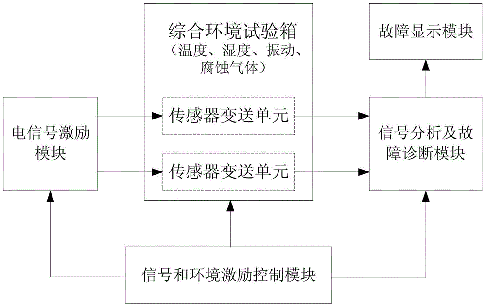
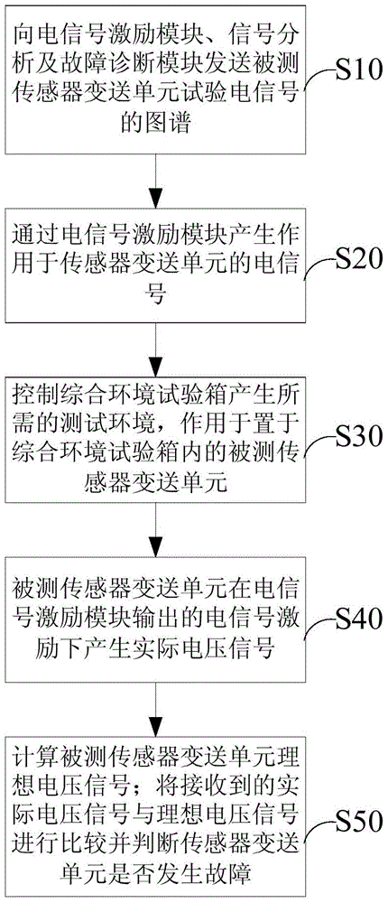
[0048] Send the test resistance signal spectrum of the transmission unit of the measured conductivity sensor to the electric signal excitation module through the signal and environment excitation control module;

[0049] A precision adjustable resistance array can be established in the electrical signal excitation module, which can simulate the various ranges of the conductivity sensor sensing unit (conductivity probe in this example) under the control of the signal and environment excitation control module, and output the corresponding resistance signal .

[0050] Send test instructions to the comprehensive environmental test chamber through the signal and environmental excitation control module, and control the comprehensive environmental ...

Embodiment 2

[0054] This embodiment takes a turbidity sensor for measuring tap water turbidity as an example. The sensor includes a turbidity probe and a turbidity sensor transmission unit; the range of the turbidity sensor is 0-40NTU, and the accuracy is ±2% (FS). The turbidity of clean tap water is generally below 5NTU. The turbidity probe outputs current signal, the output range is 4~20mA. The transmission unit of the turbidity sensor receives the current signal output by the turbidity probe, amplifies and adjusts the signal, and the output signal is a voltage signal of 1-2.5V. Send the spectrum of the tested current signal of the turbidity sensor transmission unit to the electric signal excitation module through the signal and environment excitation control module;

[0055] An mA-level current signal generator can be established in the electrical signal excitation module, which can be composed of a microcontroller, a D / A conversion chip, and a current loop circuit, etc., and can simul...


PUM


Abstract

The invention provides a sensor failure diagnosis system and diagnosis method based on signal and ambient excitation. The sensor failure diagnosis system based on signal and ambient excitation comprises an electric signal excitation module, a signal and ambient excitation control module, a signal analysis and failure diagnosis module, a failure display module and a combined environment test chamber. The electric signal excitation module is used for generating resistance signals, current signals and voltage signals and inputting the signals into corresponding measured sensor transuding units. The sensor transuding units are placed in the combined environment test chamber. The combined environment test chamber can provide a temperature environment, a humidity environment, a vibration environment and a corrosive gas environment. The signal analysis and failure diagnosis module receives voltage signals sent by the measured sensor transuding units and calculates ideal voltage signals of the measured sensor transuding units at the same time, and finally actual voltage signals and the ideal voltage signals are compared, and whether the sensor transuding units break down is judged. Through the sensor failure diagnosis system and diagnosis method, defects of sensors can be stimulated, early failure diagnosis of the sensors can be realized, and the sensor failure diagnosis system and diagnosis method have the advantages that the method is convenient and fast, and the test cost is low.

Description

technical field [0001] The invention relates to the field of sensor fault diagnosis, in particular to a sensor fault diagnosis system based on signal and environment excitation. Background technique [0002] Sensors are widely used in intelligent environmental protection, intelligent transportation, intelligent medical care, and intelligent supply chain. The quality of the sensor is also becoming more and more important. Once the sensor fails to measure and the signal of the measured object cannot be obtained correctly, the upper-level decision-making system will make a wrong judgment, resulting in the failure of the control system. The key to improving the quality level of sensors is to have advanced testing methods in the design and manufacturing stages, and to find the design and manufacturing defects of sensors through fast, low-cost, and scientific tests. In this way, the test accuracy and service life of the sensor during use can be greatly improved. [0003] At pres...

Claims


Application Information

Patent Timeline
Patent Type & Authority Patents(China)
IPC IPC(8): G01D18/00
Inventor 赵介军俞建峰过峰
Owner 江苏出入境检验检疫局机电产品及车辆检测中心
Why Eureka
Try Eureka