Welding method of tower body and skirt of a large cryogenic tower

A welding method and low-temperature tower technology, which are applied to welding equipment, workpiece edge parts, metal processing equipment, etc., can solve problems such as complex functions, increased wall thickness, and increased tower height, and achieve good controllability and good welding quality. The effect of resisting vertical load and facilitating non-destructive testing

Active Publication Date: 2016-07-06
CHINA PETROLEUM & CHEM CORP +3
View PDF5 Cites 0 Cited by
  • Summary
  • Abstract
  • Description
  • Claims
  • Application Information

AI Technical Summary

Problems solved by technology

[0004] The overlapping connection structure between the tower skirt and the tower body is difficult to be widely used because it bears shear stress and is limited by temperature
Although the stress condition of the butt connection structure is better than that of the lap connection structure, and the welded joints have a certain bearing capacity, when the tower is enlarged, the tower height, diameter, and wall thickness increase, and the height-to-diameter ratio increases. With the increase, the effect of wind load and seismic load on the tower is more complicated. In addition to the low temperature operating conditions, the force of the welded joint at the connection between the tower skirt and the tower body becomes complicated. The existing The butt connection structure can no longer meet the bearing requirements of vertical load, fatigue load resistance and low temperature brittle failure resistance

Method used


Image

  • Welding method of tower body and skirt of a large cryogenic tower
  • Welding method of tower body and skirt of a large cryogenic tower
  • Welding method of tower body and skirt of a large cryogenic tower

Examples


Embodiment Construction

[0021] The present invention will be further described in detail below in conjunction with the accompanying drawings and embodiments.

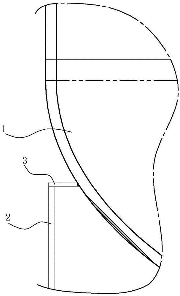
[0022] Such as Figure 1 to Figure 4 As shown, the welding method of the large-scale low-temperature tower skirt and the tower body comprises the following steps:

[0023] 1) Spot weld the annular supporting plate (3) on the lower head 1 and skirt 2 of the large cryogenic tower body; the difference between the inner diameter and the outer diameter of the annular supporting plate 3 in this embodiment is the width of the annular supporting plate A is T+60mm, T is the wall thickness of the skirt seat 2, and the thickness of the annular supporting plate 3 is 8mm.

[0024] Such as figure 1 As shown, after welding, the outer edge of the annular supporting plate 3 is connected to the upper end surface of the skirt 2, and the inner peripheral edge of the annular supporting plate 3 is connected to the outer side wall of the lower head 1;
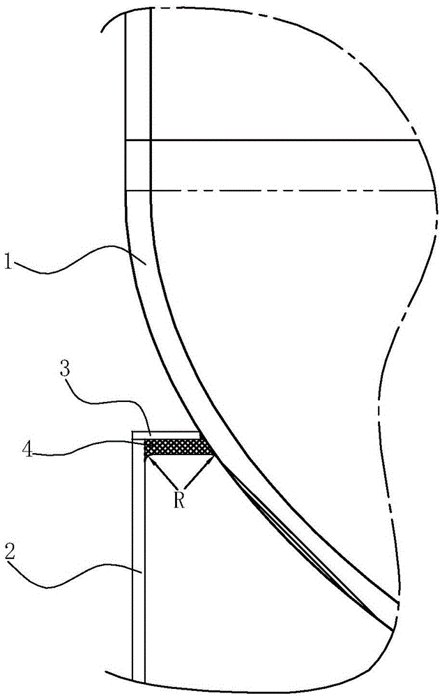
[0025] Th...


PUM

PropertyMeasurementUnit
thicknessaaaaaaaaaa
thicknessaaaaaaaaaa
thicknessaaaaaaaaaa

Abstract

The invention relates to a welding method for a tower body and a skirt seat of a large-scale low-temperature tower. The welding method is characterized by comprising the following steps of 1, spot welding an annular carrier plate to a lower end socket of the tower body and the skirt seat of the large-scale low-temperature tower, 2, carrying out lower bead weld on the lower surface of the annular carrier plate to form a lower bead weld layer and forming a chamfer with the diameter of 5mm to 20mm at the connection position between the lower end socket and the skirt seat, 3, shoveling the annular carrier plate out of the skirt seat, the lower end socket and the lower bead weld layer through a mechanical method, 4, welding an upper bead weld layer on the upper surface of the lower bead weld layer and enabling the connection position between the lower end socket and the skirt seat to be in smooth transition, and 5, detecting the welded portions and carrying out stress relief heat treatment on the welded portions after welding if the welded portions are qualified. According to the welding method, the connection structure between the skirt seat of the tower and the tower body is large in bearing size, strong in bearing capacity, good in vertical load resistance, fatigue load resistance and low-temperature brittle failure resistance, and capable of meeting the requirements for long-term safe operation of large-scale and high towers and the towers in low-temperature operation states.

Description

technical field [0001] The invention relates to a welding method for a tower body and a skirt of a large low-temperature tower. Background technique [0002] At present, for vertical self-supporting towers, there are mainly two ways of connecting the skirt and the tower body: lap joint type and butt joint type. Among them, the lap connection structure is that the skirt seat is welded to the lower head of the tower body, and can be welded to the straight edge section of the cylinder body or the head. The welding joint between the skirt seat and the tower body is a corner joint, and the inner diameter of the skirt seat cylinder With a clearance of about 4 mm from the outer diameter of the cylinder, the weld joint is offset from the circumferential weld joint of the cylinder body and head by a distance of at least 1.7 times the thickness of the cylinder. The welded joint needs to bear shear stress, and when the temperature is high or low, there is a more complex temperature fi...

Claims


Application Information

Patent Timeline
Patent Type & Authority Patents(China)
IPC IPC(8): B23K31/02B23K33/00
CPCB23K31/02B23K33/00
Inventor 杨俊岭田春霞于素艳蒋自平黄军锋段新群张忠凯
Owner CHINA PETROLEUM & CHEM CORP
Why Eureka
Try Eureka