
Cooling and heating system utilizing heat pump air conditioner and solar energy

A heat pump air conditioner and solar energy technology, which is applied in the field of cooling and heating system systems, can solve the problems of the temperature of the refrigerant not rising, the indoor temperature falling, and the high cost, and achieve the effect of improving efficiency and reliability, reducing system cost, and supplying heat smoothly.

Inactive Publication Date: 2014-08-20
何森
View PDF5 Cites 4 Cited by
  • Summary
  • Abstract
  • Description
  • Claims
  • Application Information

AI Technical Summary

Problems solved by technology

[0002] Existing heat pump air conditioners and solar cooling and heating systems have the following problems: 1) the use of solar energy for heating cannot be prioritized; 2) the heat storage of the system is not enough to effectively supplement the insufficient heat supply during the coldest time of winter night; 3) the heat pump air conditioner The machine is directly connected to the indoor end, the temperature of the refrigerant will not increase during continuous heating operation, and the heat pump cannot generate enough heat; 4) The heat pump draws heat from the indoor during defrosting, which will cause the indoor temperature to drop; 5) The system is too complicated to use a pressure water tank, High cost; 6) Unbalanced water flow at each end, uneven distribution of cold and heat in each room; 7) Complex cooling and heating conversion
[0003] From the effect of use, although the heat pump can stably heat at -15°C, many heating systems cannot meet the normal heating requirements at -5°C

Method used


Image

  • Cooling and heating system utilizing heat pump air conditioner and solar energy
  • Cooling and heating system utilizing heat pump air conditioner and solar energy

Examples


Embodiment Construction

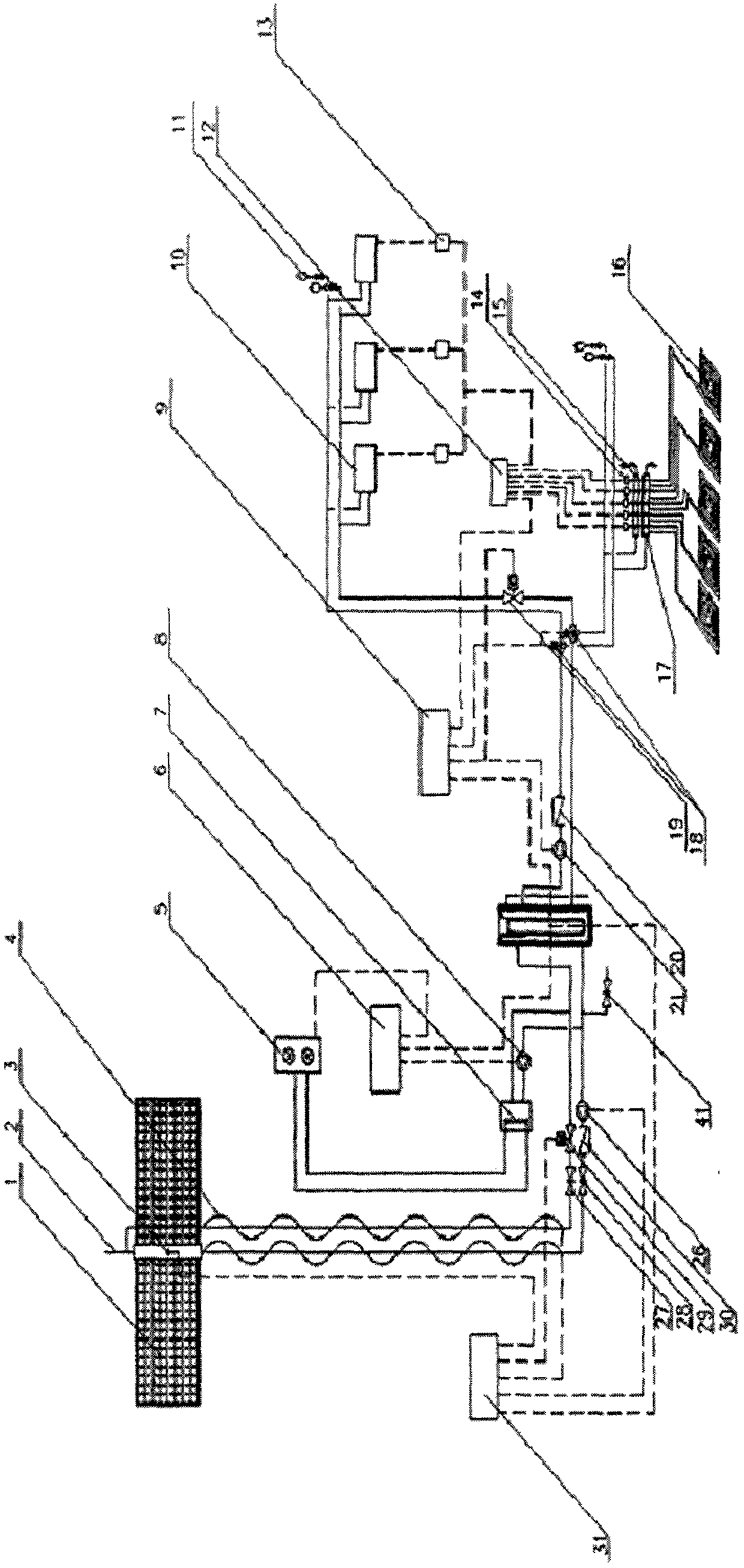
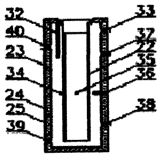
[0042] Such as figure 1 , figure 2 As shown, the solar unit part consists of a solar collector 1, an exhaust pipe 2, a collector temperature probe 3, an electric heating cable 4, a solenoid valve 29, a solar water temperature probe 35, a solar circulation pump 26, a one-way valve 30 and a solar collector. The controller 31 is composed of a water pipeline connected from the cold and heat source water outlet 39 to the cold and heat source water inlet 40 along the above path.

[0043] The heat pump air conditioner unit is composed of the heat pump air conditioner external unit 5, the fluorine water heat exchanger 7, the heat pump circulating water pump 8, the heat pump water temperature probe 34 and the heat pump air conditioner controller 6, and the cold and heat source water outlet 39 follows the above path to the cold and heat source water inlet 40.

[0044] The water tank part consists of a water tank inner barrel 23, a water tank insulation layer 24, a water tank shell 25...


PUM


Abstract

The invention discloses a cooling and heating system utilizing a heat pump air conditioner and solar energy. The cooling and heating system is characterized by comprising a solar energy unit, a heat pump air conditioner unit, a water tank and a tail end cool and heat supply unit. The solar energy unit comprises a solar heat collector, a water inlet pipeline and a water outlet pipeline, the water inlet pipeline and the water outlet pipeline are connected with the solar heat collector, an electric heat tracing band is arranged on the periphery of the water inlet pipeline and the water outlet pipeline, and the electric heat tracing band is connected with a solar controller. The water inlet pipeline and the water outlet pipeline are respectively provided with a shut-off valve, an electromagnetic valve is arranged at the downstream position of the shut-off valve of the water inlet pipeline, a check valve is arranged at the downstream position of the shut-off valve of the water outlet pipeline, and a solar circulating pump is arranged at the downstream position of the check valve. A heat collector temperature probe is arranged on the solar heat collector, and connected with the solar controller, and the water inlet pipeline and the water outlet pipeline are connected with an air discharge pipe at the tail end of the solar heat collector.

Description

technical field [0001] The present invention is a cooling and heating system, especially a heating and cooling system using heat pump air conditioner and solar energy, which uses heat pump air conditioner as cold and heat source, heat pump air conditioner and solar energy as heat source, and adopts radiant heating and fan coil unit for cooling. system. Background technique [0002] Existing heat pump air conditioners and solar cooling and heating systems have the following problems: 1) the use of solar energy for heating cannot be prioritized; 2) the heat storage of the system is not enough to effectively supplement the insufficient heat supply during the coldest time of winter night; 3) the heat pump air conditioner The machine is directly connected to the indoor end, the temperature of the refrigerant will not increase during continuous heating operation, and the heat pump cannot generate enough heat; 4) The heat pump draws heat from the indoor during defrosting, which wil...

Claims


Application Information

Patent Timeline
IPC IPC(8): F24F5/00
Inventor 何森
Owner 何森
Learn More