

Novel furnace for recovering waste heat to generate power
A new technology of waste heat power generation, applied in the direction of generators/motors, collectors, electric vehicles, etc., can solve the problems of user safety hazards, CO poisoning, insufficient fuel combustion, etc., to solve waste heat waste, low investment, and good The effect of the energy saving effect
- Summary
- Abstract
- Description
- Claims
- Application Information
AI Technical Summary
Problems solved by technology
Method used
Image

Examples
Embodiment 1
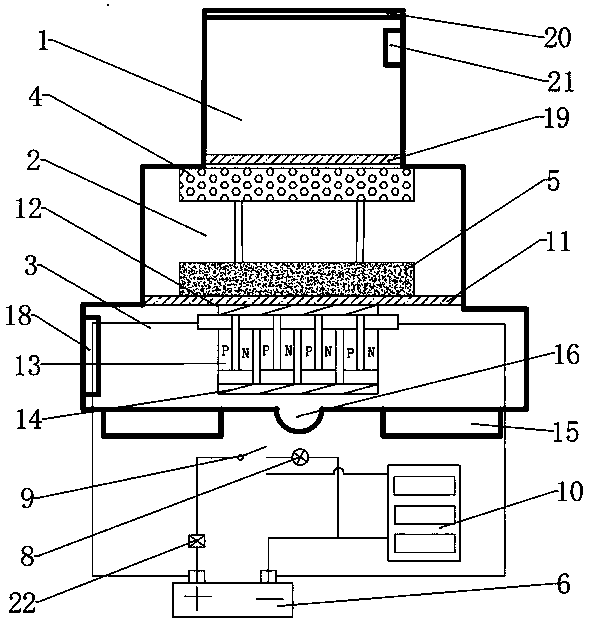
[0023] Embodiment 1: as figure 1 , Figure 4 , Figure 5 As shown in the figure, a new furnace for recovering waste heat to generate electricity includes a furnace chamber, which is divided into upper and lower layers. It is composed of an upper furnace chamber 1, a middle furnace chamber 2 and a lower furnace chamber 3. The middle furnace chamber 2 of the middle layer is the slag storage area, and the lower furnace chamber 3 of the lower layer can be the installation area of the semiconductor thermoelectric power generation device. The stability of the furnace body also increases with the decrease of the temperature of the three layers, and the increased heat transfer area is used to enhance heat transfer and improve power generation performance. An upper orifice plate 19 is provided between the upper furnace chamber 1 and the middle furnace chamber 2 , and a layered partition 11 is provided between the middle furnace chamber 2 and the lower furnace chamber 3 .
[0024] ...
Embodiment 2
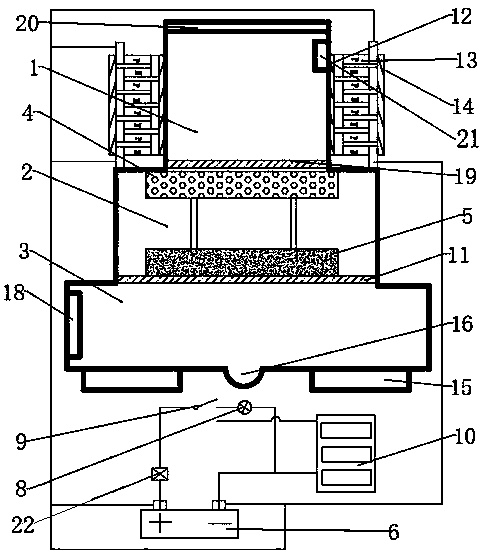
[0028] Embodiment 2: as figure 2 , Figure 4 , Figure 5As shown, a novel furnace for recovering waste heat power generation, its structure is basically the same as that of Embodiment 1, the difference is that the semiconductor thermoelectric power generation device is arranged on the outer wall of the upper chamber 1, and the semiconductor thermoelectric power generation device includes a heat absorbing layer 12, a P-N semiconductor Patch 13 and heat dissipation layer 14, the inside of P-N semiconductor patch 13 is provided with heat absorbing layer 12, the outside of P-N semiconductor patch 13 is provided with heat dissipation layer 14, and the outer wall surface of upper furnace cavity 1 is evenly provided with several columns of card slot tracks 17, Each row of card slot rails 17 has built-in evenly distributed vertical grooves, and a semiconductor thermoelectric power generation device is arranged in the vertical groove. When in use, the semiconductor thermoelectric pow...
Embodiment 3
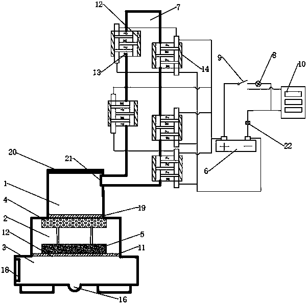
[0029] Embodiment 3: as image 3 , Figure 4 , Figure 5 As shown, a new furnace for recovering waste heat to generate electricity, its structure is basically the same as that of Embodiment 1, the difference is that the chimney mouth 21 of the upper furnace chamber 1 is connected to the chimney 7, and several semiconductors are interlacedly embedded on the wall of the chimney 7. The thermoelectric power generation device, the semiconductor thermoelectric power generation device includes a heat absorbing layer 12, a P-N semiconductor patch 13 and a heat dissipation layer 14, the P-N semiconductor patch 13 is provided with a heat absorbing layer 12 inside, and the outside of the P-N semiconductor patch 13 is provided with a heat dissipation layer 14, Heat absorbing layer 12 connects P-N semiconductor patch 13, and P-N semiconductor patch 13 connects heat dissipation layer 14, and now chimney 7, heat absorbing layer 12, P-N semiconductor patch 13, heat dissipation layer 14 const...
PUM
 Abstract
Description
Claims
Application Information