
A Digitally Controlled Regulated Inverter

A technology of digital control and digital control circuit, which is applied in the direction of converting AC power input to DC power output, output power conversion devices, electrical components, etc. , to achieve the effect of fast dynamic response, stable and reliable DC bus voltage, and easy movement

Active Publication Date: 2017-08-01
甘肃居立门业有限责任公司
View PDF3 Cites 0 Cited by
  • Summary
  • Abstract
  • Description
  • Claims
  • Application Information

AI Technical Summary

Problems solved by technology

Traditional voltage stabilizers are mainly based on autotransformers, which are bulky, large in size, and slow in dynamic response. The light ones weigh tens of kilograms, and the heavy ones can reach hundreds of kilograms. They are noisy, low in efficiency, and occupy an area when used in households. The area is large, and it brings great inconvenience to the operator during mobile operations

Method used


Image

  • A Digitally Controlled Regulated Inverter
  • A Digitally Controlled Regulated Inverter

Examples


Embodiment Construction

[0020] The present invention will be further described, explained and explained below in combination with specific embodiments.

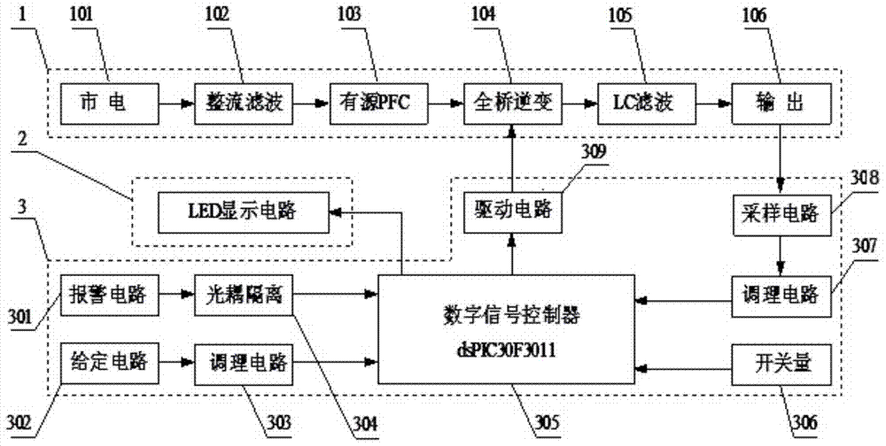
[0021] The digital control stabilized inverter of the present invention, such as figure 1 As shown, it includes a main circuit 1, an LED display circuit 2 and a digital control circuit 3 connected in sequence, and mainly includes a full-bridge inverter circuit 104. In the main circuit 1, the mains 101 is transformed into a pulsating direct current by a rectification and filtering circuit 102. After the active PFC power factor correction circuit 103, the DC pulsating voltage is boosted to 400V stable DC, and the full-bridge inverter circuit 104 is converted into high-frequency AC, and finally the high-frequency AC is shaped into a power frequency sine through the LC filter circuit 105 wave voltage.

[0022] The digital control circuit 3 takes the digital signal controller 305 as the core and includes a given circuit 302 for setting the output voltag...


PUM


Abstract

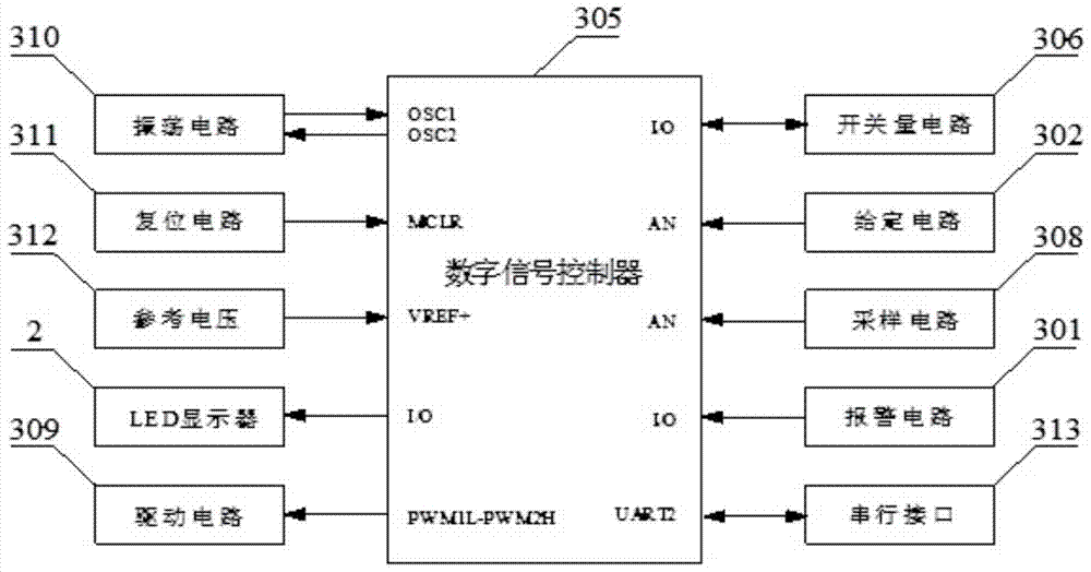
The invention relates to a digital voltage stabilizing inverter, in particular to a digital control voltage stabilizing inverter which is high in power factor and precise in output voltage. The inverter comprises an active power factor correcting (PFC) circuit, a full-bridge inverter circuit and a digital control system. The active power factor correcting circuit and the full-bridge inverter circuit form a main circuit of the inverter. A digital signal controller dsPIC30F3011 is adopted to serve as a corn control unit of the digital control system. Full-digital pulse width modulation (PWM) is achieved through a drive system of the full-bridge inverter circuit to control an output voltage outer loop and a current inner loop. A man-machine interaction system displays output voltage in real time, and meanwhile reliable work of the inverter is effectively guaranteed through compact over-current, over-voltage / under-voltage and overheat protection circuits. Besides, the inverter further comprises a current sampling circuit and a voltage sampling circuit, the current sampling circuit and the voltage sampling circuit transmit signals to the digital signal controller by being connected with an auxiliary circuit and a signal modulation circuit respectively, and the main circuit system is regulated and controlled through the current sampling circuit, the voltage sampling circuit and the drive circuit.

Description

technical field [0001] The invention relates to the technical field of power electronics, in particular to a digitally controlled voltage stabilizing inverter. [0002] technical background [0003] A voltage stabilizer is a power supply circuit or power supply equipment that can automatically adjust the output voltage. Its function is to stabilize the voltage that fluctuates greatly or does not meet the operating requirements of electrical equipment within its set value range, so that various circuits or Electrical equipment can work normally under the rated working voltage. Traditional voltage stabilizers are mainly based on autotransformers, which are bulky, large in size, and slow in dynamic response. The light ones weigh tens of kilograms, and the heavy ones can reach hundreds of kilograms. They are noisy, low in efficiency, and occupy an area when used in households. The area is large, and it brings great inconvenience to the operator during the mobile operation. [0...

Claims


Application Information

Patent Timeline
Patent Type & Authority Patents(China)
IPC IPC(8): H02M7/5395H02J3/18
CPCY02E40/30
Inventor 张海荣张海龙
Owner 甘肃居立门业有限责任公司
Learn More