
A multi-antenna configuration and channel allocation method suitable for wireless data center networks

A wireless data center and channel allocation technology, applied in wireless communication, network planning, electrical components, etc.

Active Publication Date: 2017-06-13
TSINGHUA UNIV
View PDF1 Cites 0 Cited by
  • Summary
  • Abstract
  • Description
  • Claims
  • Application Information

AI Technical Summary

Problems solved by technology

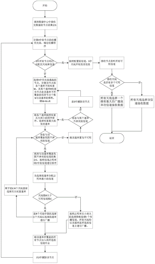
[0006] In order to overcome the shortcomings of the above-mentioned prior art, the purpose of the present invention is to provide a multi-antenna configuration and channel allocation method suitable for wireless data center networks, which solves the problem of mutual matching between antennas and channels in wireless data centers, and realizes the multi-antenna configuration and channel allocation method in wireless data centers. Freely allocate different channels on the fixed antenna to maximize the wireless transmission bandwidth in the data center network

Method used


Image

  • A multi-antenna configuration and channel allocation method suitable for wireless data center networks
  • A multi-antenna configuration and channel allocation method suitable for wireless data center networks

Examples


Embodiment Construction

[0030] The implementation of the present invention will be described in detail below in conjunction with the drawings and examples.

[0031] First, let's introduce the wireless interference model. In wireless transmission, each wireless transmitting antenna has a certain transmission effective range and transmission interference range. The transmission interference range of a wireless antenna is often about twice as large as its transmission effective range. If a receiving antenna is in the transmission interference range of two transmitting antennas, the data it receives will be corrupted. Therefore, the transmission interference range of the wireless antenna can be defined as its transmission coverage.

[0032] In addition, the coverage area of ​​the wireless antenna will also vary according to the transmission rate. When a wireless antenna transmits at a lower rate, it covers a larger area; when it broadcasts at a higher rate, it covers a smaller area. How to make a pro...


PUM


Abstract

Disclosed is a multi-antenna configuration and channel distribution method applicable to a wireless data center network. The method includes the following steps: finding out all nodes which finish receiving of all data and using the nodes as nodes which are to send data in the next step; selecting a node which carries out data multicast most firstly and according to coverage ranges under different rates of the node, finding out an adjacent node set of the node, wherein the adjacent node set is effective in transmission under the rates, and obtaining a weight of each transmission rate through calculation; firstly, selecting a channel for a rate which has the largest weight; ranking channels, which do not conflict with the rate, in an aggregated-data center network; then according to the weights, distributing channels for antennae of all nodes which are to carry out multicast; and all antennae which obtain the channels sending data and reception nodes monitoring all available channels and carrying out reception according to the condition. The multi-antenna configuration and channel distribution method solves a problem of mutual matching of the antennae and the channels of a wireless data center and realizes free distribution of the different channels on the antennae of a fixed number so that the wireless transmission bandwidth in the data center network is improved to the largest degree.

Description

technical field [0001] The invention belongs to the technical field of wireless channel allocation, in particular to a multi-antenna configuration and channel allocation method suitable for wireless data center networks. Background technique [0002] Since the rise of cloud computing, data center network has become a current research hotspot. With the birth of high-speed wireless transceivers, the corresponding protocols have gradually been proposed by the standards association. Among them, 802.11ac and 802.11ad have become the mainstream of next-generation wireless communication protocols. Today, antenna manufacturing technology is becoming more and more mature, and the cost of high-speed wireless transceivers is getting lower and lower, and they are widely used in various aspects of wireless transmission. [0003] Kandula and others first proposed to apply wireless receivers to the data center network, that is, to install wireless transceivers on the racks to assist trad...

Claims


Application Information

Patent Timeline
Patent Type & Authority Patents(China)
IPC IPC(8): H04W16/14H04W72/04
Inventor 崔勇朱超肖诗汉
Owner TSINGHUA UNIV
Learn More