Light source lifetime extension in an optical system

An optical system and light source technology, applied in the field of optical systems, can solve problems such as difficult to obtain and complex

Active Publication Date: 2014-08-20
F HOFFMANN LA ROCHE & CO AG
View PDF7 Cites 5 Cited by
  • Summary
  • Abstract
  • Description
  • Claims
  • Application Information

AI Technical Summary

Problems solved by technology

This however requires temperature measurement and precise temperature control,...

Method used


Image

  • Light source lifetime extension in an optical system
  • Light source lifetime extension in an optical system
  • Light source lifetime extension in an optical system

Examples


Embodiment Construction

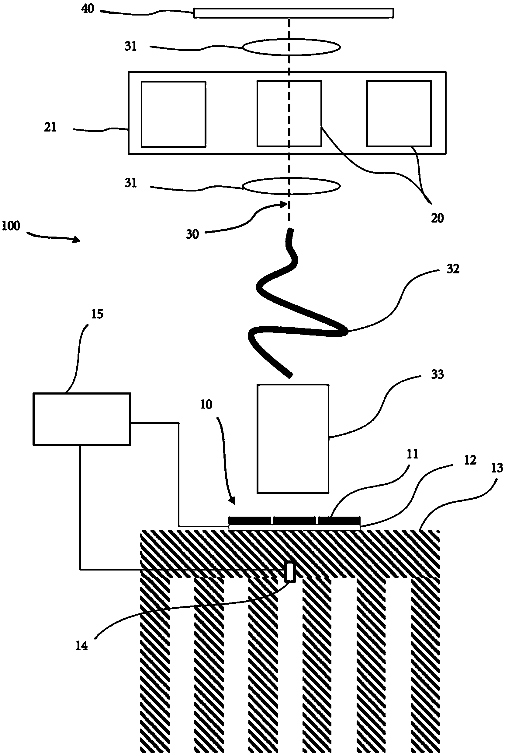
[0057] figure 1 An optical system 100 for photometric measurement of a sample is depicted schematically and not to scale, for example, for determining the concentration of an analyte contained in a sample contained in an optical cuvette 20 held on a cuvette holder 21. presence and / or concentration. The cuvette holder 21 is in this case a rotating body carrying a plurality of cuvettes 20 and conveys one cuvette at a time to the light path 30 during rotation. System 100 includes optical path components such as lenses 31, glass fiber bundles 32, mixing rods 33, and possibly other (not shown) components such as apertures, mirrors, diffraction gratings. The system 100 further includes an optical detector 40 comprising an optical sensor such as a CCD sensor that converts electromagnetic energy of light from the cuvette 20 positioned on the optical path 30 into an electrical signal. The sensor 40 may be divided into several (not shown) sections, each dedicated to one of the availab...


PUM


Abstract

An optical system comprising a light source comprising a plurality of light emitting elements (LEEs) is presented. The light source is mounted on the same substrate or chip board so that the LEEs are in thermal contact with each other such as to enable thermic conduction and heat transfer between the LEEs. The system is switchable between light source modes in which different light emitting elements or a different number of light emitting elements is switched in an on mode and in a down mode respectively. In all light source modes, one or more light emitting elements, such as those with longer expected lifetime, remain in the on mode, while one or more light emitting elements, such as those with shorter expected lifetime, may be switched in the down mode.

Description

technical field [0001] The invention relates to the field of optical systems for photometric measurement of samples, wherein said system comprises a light source comprising a plurality of light emitting elements, and to a method of controlling the light source. Background technique [0002] Various types of tests related to patient diagnosis and treatment can be performed through the analysis of patient fluid samples. Such samples are typically placed in sample tubes. For analysis, they are extracted from the tubes, combined with various reagents, incubated, and analyzed. In a typical analysis in clinical chemistry and immunochemistry, one or more assay reagents are added to a liquid sample, the sample-reagent-compound is mixed and incubated in an optical cuvette. During the course of the reaction changes in optical properties occur, such as changes in the absorption, scattering or fluorescence of the sample. Often optical systems are used to perform photometric measureme...

Claims


Application Information

Patent Timeline
IPC IPC(8): G01J1/08G01J3/02G01J3/10H01L33/64H01L25/075H05B44/00
CPCG01N21/17G01N21/01G01J1/08H05B33/0821G01J3/0286G01J3/10H05B47/17
Inventor R.哈勃斯P.N.泽勒
Owner F HOFFMANN LA ROCHE & CO AG
Why Eureka
Try Eureka