Mechanical cleaning system for underground storage tank of filling station

A technology for mechanical cleaning and gas station, which is applied to the field of mechanical cleaning system for buried oil tanks in gas stations, can solve the problems of large area of ​​the whole system, centralized venting, complicated separation and processing equipment of cleaning products, etc., and achieves the effect of compact structure

Active Publication Date: 2014-08-27
BEIJING INSTITUTE OF PETROCHEMICAL TECHNOLOGY
View PDF8 Cites 30 Cited by
  • Summary
  • Abstract
  • Description
  • Claims
  • Application Information

AI Technical Summary

Problems solved by technology

[0007] The purpose of the present invention is to provide a mechanical cleaning system for buried oil tanks in gas stations that is intrinsically safe, fully closed, efficient and environmentally friendly, and compact in structure, so as to overcome the volatile, toxic and harmful gases that exist in the existing mechanical cleaning systems for buried oil tanks in gas stations (Oil and gas, etc.) Disorderly discharged or finally concentrated emptying, oily sewage failed to meet the standard treatment, cleaning product separation and treatment equipment is complex, the entire system occupies a large area, etc.

Method used


Image

  • Mechanical cleaning system for underground storage tank of filling station
  • Mechanical cleaning system for underground storage tank of filling station
  • Mechanical cleaning system for underground storage tank of filling station

Examples


specific Embodiment

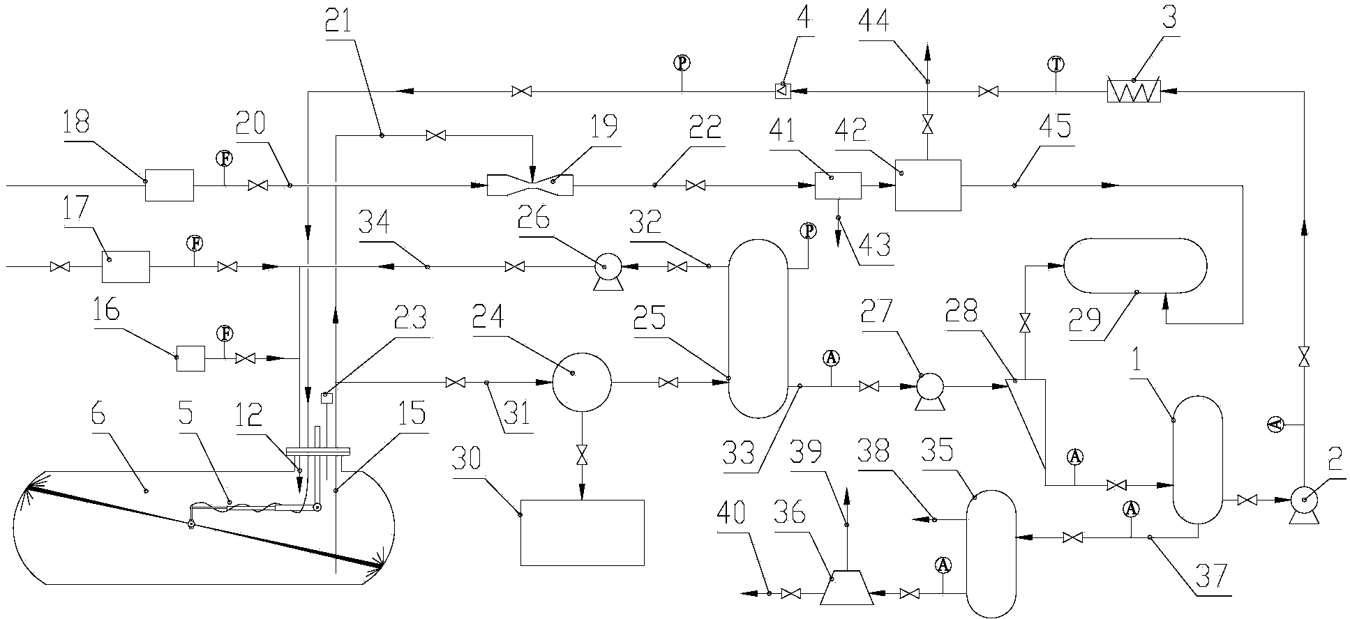
[0042] Such as figure 1 , figure 2As shown, the system mainly includes low-pressure jet cleaning equipment, air replacement equipment, gas atmosphere monitoring equipment, cleaning product separation treatment and recycling equipment, oily sewage outflow compliance treatment equipment and oil gas recovery treatment equipment, etc.

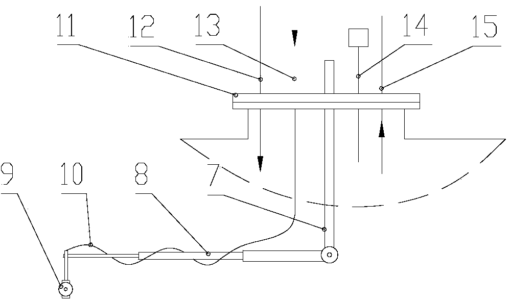
[0043] image 3 It is a schematic diagram of the installation of the washing machine on the special matching sealing cover. The special matching sealing cover 11 is also integrated with a nitrogen injection pipe joint 12, a water supply pipe joint 13, a gas atmosphere monitoring sampling pipe joint 14 and a suction pipe joint 15, which greatly facilitates Each pipeline is connected to the cleaning machine and ensures that the cleaning process is carried out in a closed state.

[0044] The low-pressure spray cleaning equipment includes a water storage tank 1, a booster pump 2, a heater 3, a turbine flowmeter 4 and a washing machine 5, and each pa...


PUM

PropertyMeasurementUnit
separationaaaaaaaaaa

Abstract

The invention discloses a mechanical cleaning system for an underground storage tank of a filling station. The mechanical cleaning system comprises a low-pressure jet cleaning device, an air replacement device, a gas atmosphere monitoring device, a cleaned-away dirt separation and recycling device, an oily sewage discharge standardization treatment device and an oil and gas recovery treatment device. The low-pressure jet cleaning device comprises a water storage tank, a booster pump, a heater, a turbine flowmeter and a cleaning machine, wherein the water storage tank, the booster pump, the heater, the turbine flowmeter and the cleaning machine are connected in sequence through pipelines. The air replacement device comprises a nitrogen generator, an air heater and an oilless air compressor. The oil and gas recovery treatment device comprises a precooler and an activated carbon adsorption tank, wherein the precooler and the activated carbon adsorption tank are connected with each other. The cleaned-away dirt separation and recycling device comprises a filter, a vacuum suction tank, a suction pump and an axial inlet hydrocyclone. The oily sewage discharge standardization treatment device comprises a compact vertical swirling air-floatation separation tank and a disk centrifuge. The mechanical cleaning system is intrinsically safe, efficient, environmentally friendly, compact in structure and capable of meeting related discharge requirements.

Description

technical field [0001] The invention relates to a technology for mechanical cleaning of oil tanks and recovery and treatment of sewage and oil gas, in particular to a mechanical cleaning system for buried oil tanks in gas stations. Background technique [0002] Gas stations are an important link in the petroleum industry chain and value chain. Usually, each gas station has at least two Underground Storage Tanks (UST). According to the "Safety Technical Regulations for Oil Tank Cleaning" (Q / SH039-013-1998), in order to ensure product quality, regularly inspect and maintain the internal facilities of the storage tank, and also create conditions for retesting the storage tank and reprogramming the volume meter, the gas station Buried oil tanks generally need to be cleaned regularly every 3-5 years; in addition, there are irregular cleanings of buried oil tanks in gas stations, for example, when the oil tank is changed to store another type of oil and the properties of the two a...

Claims


Application Information

Patent Timeline
Patent Type & Authority Applications(China)
IPC IPC(8): B08B9/093B08B13/00
CPCB01D5/0057B01J19/14B08B9/0936C02F1/24C02F1/38C02F9/00
Inventor 陈家庆石熠刘美丽
Owner BEIJING INSTITUTE OF PETROCHEMICAL TECHNOLOGY
Why Eureka
Try Eureka