Construction method for cast-in-situ foam separation wall for tailing filling mining

A filling mining and construction method technology, which is applied in the direction of filling, mining equipment, earth square drilling, etc., can solve the problems of non-recycling, difficult quicksand isolation, difficult recycling and reuse, etc., and achieve good shock resistance and impact resistance. Good economic benefits and the effect of making up for construction costs

Inactive Publication Date: 2014-08-27
YANTAI UNIV
View PDF5 Cites 14 Cited by
  • Summary
  • Abstract
  • Description
  • Claims
  • Application Information

AI Technical Summary

Problems solved by technology

This method is characterized by high construction efficiency, but its disadvantages are: (1) All construction materials will be scrapped after filling and cannot be recycled; (2) 0.5m-1.0m must be reserved for the next mining route It is not only technically difficult to realize the mine wall, but even if it can be realized, it is still difficult to prevent the tailings filling from collapsing when the mine wall is finally found out, so the problem of ore dilution cannot be solved
However, the separation wall in this way still has the following problems: (1) because

Method used


Image

  • Construction method for cast-in-situ foam separation wall for tailing filling mining

Examples


Embodiment 1

[0031] Embodiment 1 is used for the construction method of cast-in-place foam separation wall for tailings filling mining, and the steps are as follows:

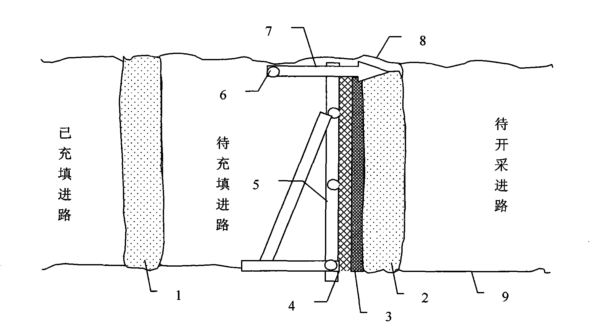
[0032]Step 1: Clean the bottom plate and build scaffolding 5 on the side of the gob approach near the concrete wall of the road to be mined, within 0.4-0.8m, preferably 0.5-0.6m, of the concrete wall along the approach. The spacing between the vertical steel pipes of the scaffold is 0.8-1.5m, preferably 0.8-1.0m. Before setting up, use a rock drill to drill a hole of 0.3-0.5m on the floor, and then insert the vertical steel pipes into it; the spacing of the horizontal steel pipes is 0.5m. -1.5m, preferably 0.7-0.8m, among them, two horizontal steel pipes should be used at the bottom, and the distance from the bottom plate should not exceed 10cm.

[0033] Step 2: Use a hook, or thin iron wire, or use a thin rope to fix Chenglishan 4 to the scaffold 5, and then hang and paste the isolation cloth 3 on Chenglishan 4, and place i...

Embodiment 2

[0037] Example 2 In a gold mine, an upward horizontal approach is adopted for layered mining, and the section size of a single approach is 4m wide and 3m high. The extension length of a single entry is generally 300m-400m, and the daily depth is about 30m. In the past, high-water cement glue ending sand-type cemented filling with a lime-sand ratio = 1:20, and a 1:10 lime-sand roofing process were used, and the overall cost was 40 yuan / m 3 The comprehensive cost per m depth is about 480 yuan.

[0038] Now use the foam separation wall-water sand filling method (construction method of cast-in-place foam separation wall for tailings filling mining), the specific implementation process is:

[0039] Step 1: Clean the bottom plate and build scaffolding on the side of the goaf approach that is close to the concrete wall of the road to be mined, and within an average range of 0.6m from the concrete wall along the approach. Among them, the distance between the vertical steel pipes of ...


PUM

PropertyMeasurementUnit
Compressive strengthaaaaaaaaaa
Flexural strengthaaaaaaaaaa
Compressive strengthaaaaaaaaaa

Abstract

The invention provides a construction method for a cast-in-situ foam separation wall for tailing filling mining. The construction method comprises the following steps of: step 1, clearing a bottom plate and setting up a scaffold at the solid side of a mined-out inlet channel close to an inlet channel to be mined; step 2, fixing a force-bearing grating on the scaffold, and then hanging and bonding a separation cloth on the force-bearing grating; step 3, fixing the scaffold coated with the force-bearing grating and the separation cloth by a diagonal bracing, and surrounding a cavity with an open upper portion among the solid side, the bottom plate and the scaffold; step 4, injecting foam slurry in the cavity, and after the foam slurry is solidified to achieve a certain strength, detaching the scaffold, removing the force-bearing grating, and then obtaining the cast-in-situ foam separation wall. The construction method is rapid in construction, convenient to pour, and good in application performance.

Description

technical field [0001] The invention belongs to the technical field of mining filling, and in particular relates to a construction method for quickly building a cast-in-place foam separation wall for tailings filling mining. Background technique [0002] At present, for the mining of high-grade and thick ore seams, the filling and filling mining method is generally adopted. According to different filling materials, it can be divided into three types: dry filling method, water sand filling method and cemented filling method. Among them, the dry filling method is to use various transport machinery to transport the waste ore to the goaf for filling. Due to the low production efficiency, it is rarely used now; the water-sand filling method uses pumping or self-flowing methods to transport the high-water tailings solid-liquid mixture to the gob, and passes through the tailings after the water is filtered out. Filling achieved by deposition. The cemented filling method is to mi...

Claims


Application Information

Patent Timeline
IPC IPC(8): E21F15/04
Inventor 徐惠忠郝旭彬吴加旭王江涛
Owner YANTAI UNIV
Why Eureka
Try Eureka