Steam direct pressure type drying device of veneer materials

A drying device and steam technology, applied in the direction of static material dryer, drying gas arrangement, local stirring dryer, etc., can solve the problems of high energy consumption and expensive equipment, and achieve less heat loss, fast drying speed and high efficiency Effect

Inactive Publication Date: 2014-08-27
黄达宏
View PDF8 Cites 5 Cited by
  • Summary
  • Abstract
  • Description
  • Claims
  • Application Information

AI Technical Summary

Problems solved by technology

The characteristics of this type are: the heat energy is transmitted to the material by the steel plate, and the efficiency depends on the size of the contact surface, pressure and temperature difference. This type of equipment can achieve fast drying speed and high output, but the corresponding equipment is more expensive. Energy consumption is also large

Method used


Image

  • Steam direct pressure type drying device of veneer materials
  • Steam direct pressure type drying device of veneer materials
  • Steam direct pressure type drying device of veneer materials

Examples


Embodiment 1

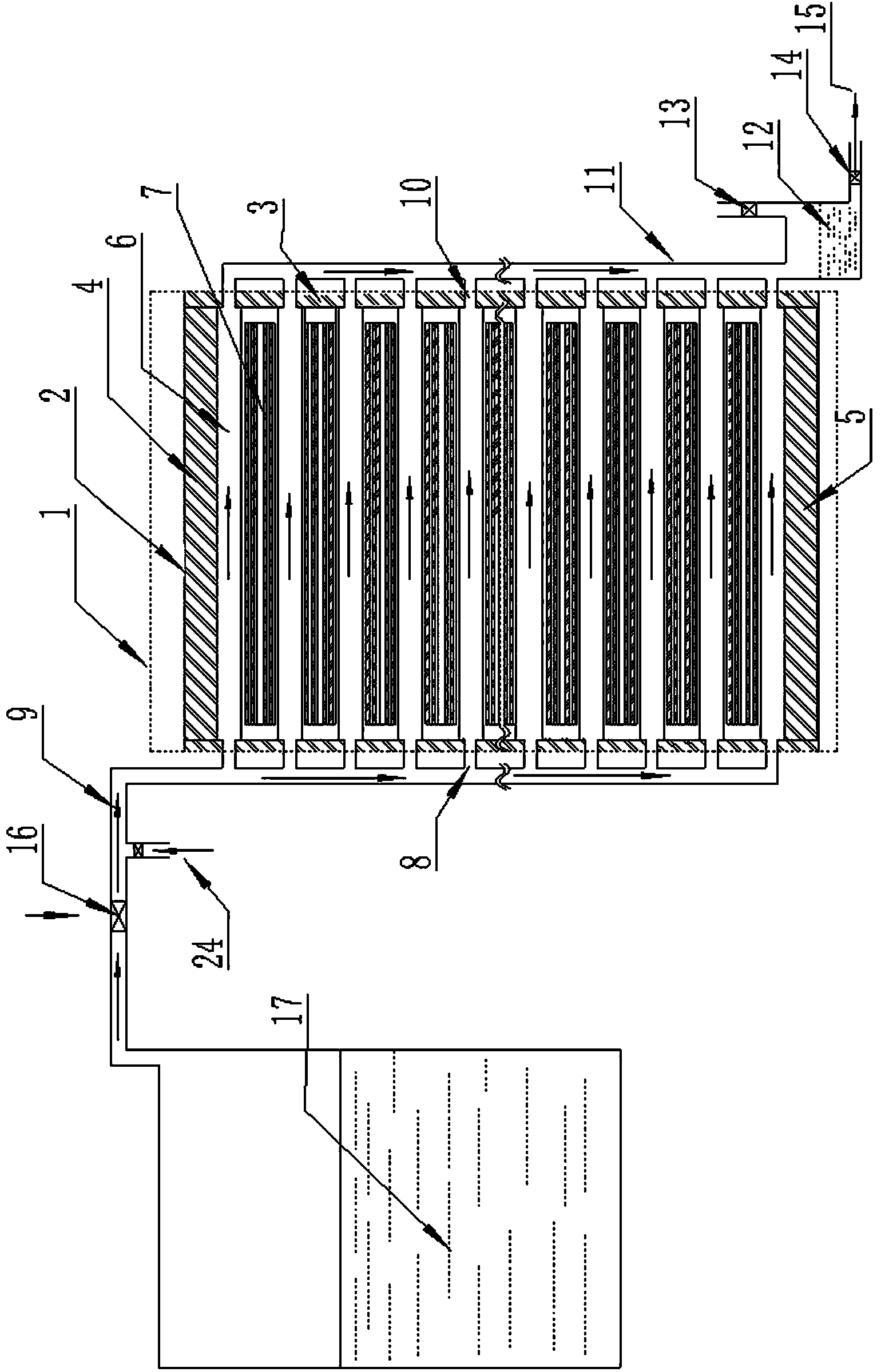
[0028] refer to figure 1 , figure 2 and image 3 , a steam direct pressure type veneer material drying device, comprising a drying box 1, a steam boiler, a steam supply pipe 9 connecting the drying box 1 and the steam boiler and a valve 16 arranged on the steam supply pipe 9, the periphery of the drying box 1 There is a heat insulation layer, and a drying rack 2 is arranged in the drying box 1. The drying rack 2 is placed horizontally in the drying box 1. The top and bottom layers of the drying rack 2 are the upper pressure limit plate 4 and the lower bearing made of steel plates. The pressure limiting plate 5 is fixedly connected with the connecting rod 3 arranged between the upper and lower pressure limiting plates, and the same stainless steel plate is arranged in parallel at equal intervals to make the surrounding closed. Hollow heating plate 6, the side of heating plate 6 of each layer is fixedly connected with connecting rod 3, is provided with steam inlet 8 on the sa...

Embodiment 2

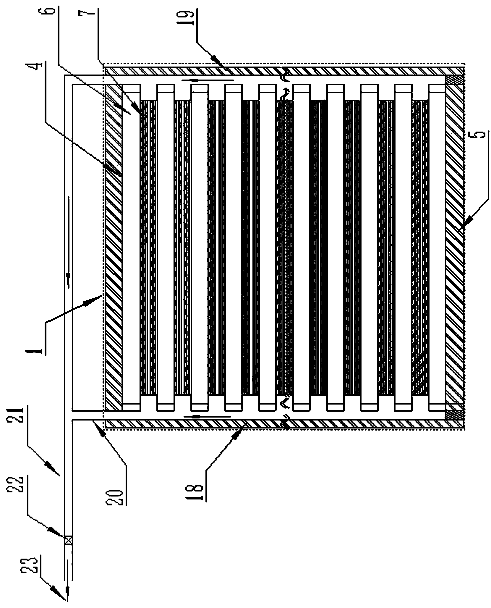
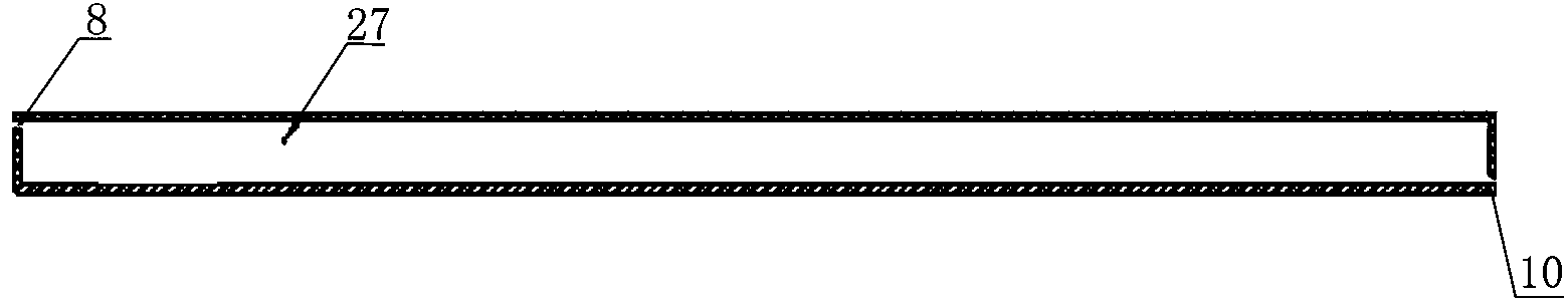
[0035] refer to image 3 , Figure 4 and Figure 5, a steam direct pressure type veneer material drying device, the difference from embodiment 1 is: the drying rack 2 is vertically placed in the drying box 1, and the left and right sides are left pressure limiting plates 25 made of steel plates With the right pressure limiting plate 26, the connecting rod 3 is fixedly connected between the left and right pressure limiting plates, and the same spacing is arranged in parallel between the left and right pressure limiting plates. Hollow heating plates 6 closed all around, the upper and lower sides of each heating plate 6 are fixedly connected with the connecting rod 3, and the upper end surface of each heating plate 6 is provided with a steam inlet 8, and the connecting pipe of the steam inlet 8 communicates with the boiler steam supply pipe 9 , steam can pass into the heating plate inner cavity 27, and the lower end surface of each heating plate 6 is provided with a gas-liquid ...


PUM


Abstract

The invention discloses a steam direct pressure type drying device of veneer materials. The steam direct pressure type drying device of the veneer materials comprises a drying oven, a steam boiler and a steam air supply pipe connecting the drying oven and the steam boiler. A horizontally arranged drying frame is arranged in the drying oven, the top layer and the bottom layer of the drying frame are an upper pressure bearing limiting plate and a lower pressure bearing limiting plate which are made of steel plates respectively, a connecting rod is arranged between the limiting plates and fixedly connected with the limiting plates, enclosed hollow heating plates made of stainless steel sheets are arranged between the limiting plates at intervals in parallel, the side edges of all layers of heating plates are fixedly connected with the connecting rod, a steam inlet connecting pipeline is arranged on the same side face of the heating plates and is communicated with the boiler steam air supply pipe, a gas-liquid inlet connecting pipeline is arranged on the other side face of the heating plates and is communicated with a gas-liquid water outlet pipe, and the gas-liquid water outlet pipe is communicated with a water storage tank. According to the steam direct pressure type drying device of the veneer materials, the heat energy for drying the materials is transmitted to the materials through the steam and is separated from the materials only through a thin layer of stainless steel sheet, and pressure is directly provided by the steam, so that a mechanism for providing pressure and energy consumption are omitted, the device is compact in structure, and the defects that an existing device is high in manufacturing cost and large in energy consumption are overcome.

Description

technical field [0001] The invention relates to the field of heat energy application, in particular to a steam direct-pressure veneer material drying device which utilizes high-temperature and high-pressure steam from a boiler to provide both heat energy and pressure. Background technique [0002] In wood processing, there is a process of cutting the felled logs into certain specifications of raw wet wood chips, that is, veneers. These veneers are then dried, usually in the sun or dried for easy transportation, storage or further processing. Existing drying equipment can be divided into two categories, one is to use air convection to transfer heat energy to materials, there are drying rooms, tunnel drying lines, etc. The disadvantages are large space occupation, high heat dissipation, slow speed and low efficiency . The other type is to transfer heat energy to materials by means of heat conduction between solids. For example, multi-layer hot-press dryers use boiler steam o...

Claims


Application Information

Patent Timeline
Patent Type & Authority Applications(China)
IPC IPC(8): F26B9/06F26B21/00
Inventor 黄达宏
Owner 黄达宏
Why Eureka
Try Eureka