Direct-current transmission protection device, current converter and protection method

A technology for DC transmission protection and protection devices, which is applied to emergency protection circuit devices, emergency protection devices with automatic disconnection, circuit devices, etc., can solve problems such as oscillation and short-circuit current attenuation difficulties, and achieve suppression of DC short-circuit current and shorten The effect of shortening the DC stop time and decay time

Active Publication Date: 2014-08-27
NR ELECTRIC CO LTD +1
View PDF5 Cites 21 Cited by
  • Summary
  • Abstract
  • Description
  • Claims
  • Application Information

AI Technical Summary

Problems solved by technology

[0011] The purpose of the present invention is to provide a DC transmission protection device, a converter and a protection method, which can effectively solve the inherent defects of difficult short-circuit current attenuation and oscillation in flexible DC transmission systems, and are simple to implement and economical

Method used


Image

  • Direct-current transmission protection device, current converter and protection method
  • Direct-current transmission protection device, current converter and protection method
  • Direct-current transmission protection device, current converter and protection method

Examples


Embodiment Construction

[0034] The technical solutions of the present invention will be described in detail below in conjunction with the accompanying drawings.

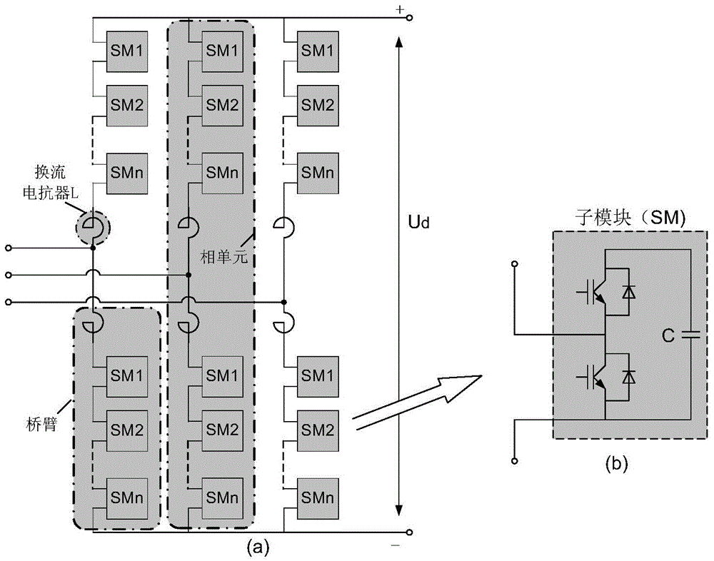
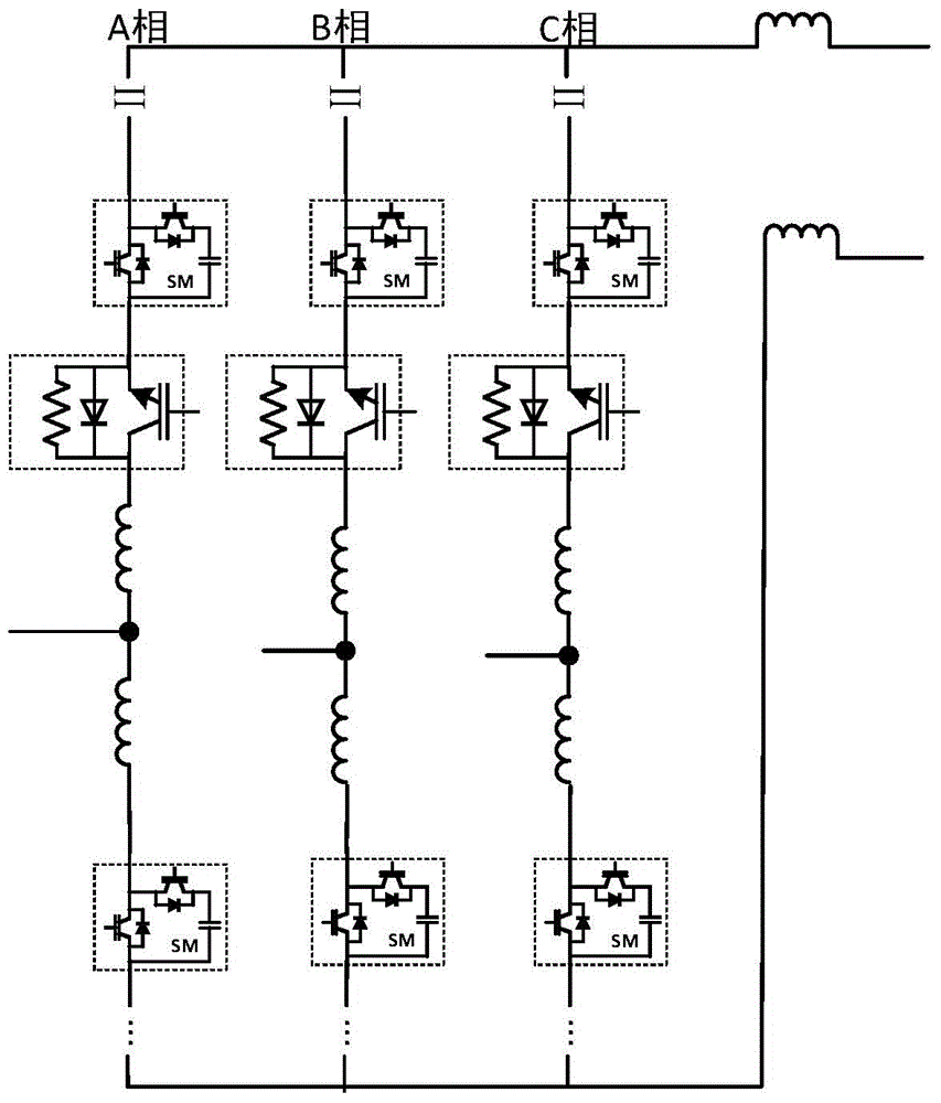
[0035] Such as figure 1 Shown is a converter topology. The converter includes three phases, and each phase includes upper and lower bridge arms, consisting of 6 bridge arms in total. Each bridge arm is composed of a reactor L and N sub-modules SM in series, and the upper and lower bridge arms of each phase are combined to form a phase unit. The point where the upper and lower arms join is called the midpoint. The leading ends of the three upper bridge arms are connected together, which is the positive end of the converter; the leading ends of the three lower bridge arms are connected together, which is the negative end of the converter.

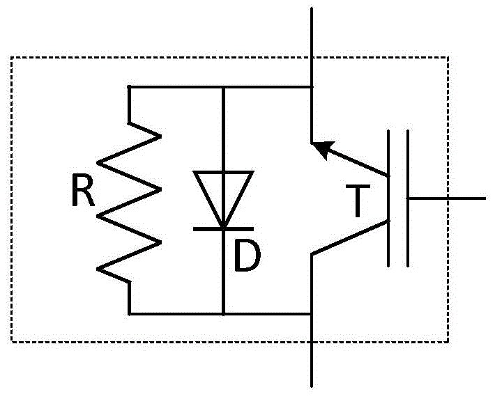
[0036] The present invention provides a protection device, which includes a resistance unit and a bidirectional flow current switch unit, and the protection device is formed by connecting the resistance...


PUM


Abstract

The invention discloses a direct-current transmission protection device comprising a resistor unit and a two-way circulation current switch unit. The protection device is formed by connecting the resistor unit and the two-way circulation current switch unit in parallel, wherein the resistor unit is formed by at least one resistor in a cascade connection mode; the two-way circulation current switch unit is formed by at least one two-way circulation current switch in a cascade connection mode. The invention further provides a current converter comprising the protection device, and each phase unit is connected with at least one protection device in series. The invention further provides a protection method of the current converter. Vibration of direct current short-circuit current and damping current can be restrained rapidly and effectively, equipment is protected better, fault current fall time is shortened greatly, and therefore the direct current outage time is shortened. Furthermore, economic losses and system instability risk caused by outage are reduced to the maximum extent. Meanwhile, the direct-current transmission protection device is simple in structure and low in cost, and has good realizability and economical efficiency.

Description

technical field [0001] The invention belongs to the field of DC power transmission, and in particular relates to a protection device for DC short-circuit faults in flexible DC transmission, a converter formed by using the protection device, and a protection method thereof. Background technique [0002] Direct current transmission technology (HVDC, High-Voltage Direct Current) is a kind of high-power semi-controlled power electronic devices (such as thyristors) or fully-controlled power electronic devices (such as insulated gate bipolar transistors (IGBT, Insulated Gate Bipolar Transistor) , Integrated Gate Commutated Thyristors (IGCT, Intergrated Gate Commutated Thyristors), etc.) to achieve AC / DC and DC / AC conversion, thereby transmitting power energy in the form of DC transmission technology. Among them, the DC transmission using the semi-controlled power electronic device thyristor is called the current source converter-based DC transmission system (CSC-HVDC), also known ...

Claims


Application Information

Patent Timeline
Patent Type & Authority Applications(China)
IPC IPC(8): H02H3/087H02H7/125H02M7/217
CPCH02M1/32H02H7/10H02H7/1227H02H7/1257H02H7/127H02M7/4835Y02E60/60H02H3/202H02H7/1252H02M7/2173H05K7/20927
Inventor 曹冬明谢晔源邵震霞卢宇李敏刘海彬李海英
Owner NR ELECTRIC CO LTD
Why Eureka
Try Eureka