A three-phase U-shaped stator tooth external rotor switched reluctance motor and its driving method

The technology of a switched reluctance motor and its driving method is applied in the direction of electrical components, electromechanical devices, starting devices, etc., and can solve the problems of a large number of switching devices in a power converter, complex stator winding connections, and high system costs, and achieve switching Fewer components, suitable for low-speed applications, simple topology

Active Publication Date: 2017-03-22
冬雷
View PDF4 Cites 0 Cited by
  • Summary
  • Abstract
  • Description
  • Claims
  • Application Information

AI Technical Summary

Problems solved by technology

The traditional switched reluctance motor has concentrated windings on each stator pole, and the windings on two radially opposite stator poles form a stator winding. The more phases of the motor, the more complicated the wiring of the stator winding, and the control will also be It becomes complicated, and the number of switching devices in the power converter is large, and the system cost is high

Method used


Image

  • A three-phase U-shaped stator tooth external rotor switched reluctance motor and its driving method
  • A three-phase U-shaped stator tooth external rotor switched reluctance motor and its driving method
  • A three-phase U-shaped stator tooth external rotor switched reluctance motor and its driving method

Examples


Embodiment 1

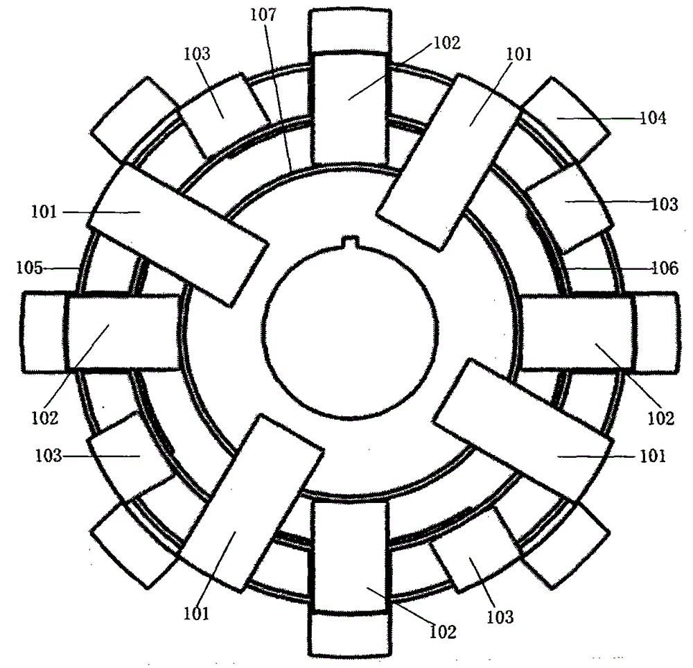
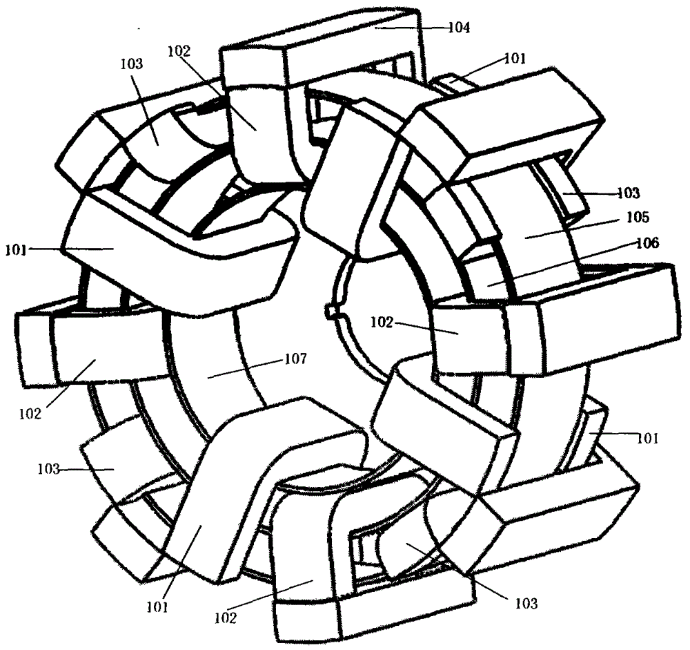
[0026] Such as figure 1 , figure 2As shown, a three-phase U-shaped stator tooth external rotor switched reluctance motor includes a first stator (101), a second stator (102), a third stator (103), a rotor (104) and a first winding ( 105), the second winding (106), the third winding (107), the first stator (101), the second stator (102), and the third stator (103) have 12 in total, using three different sizes U-shaped teeth, 4 of each size stator teeth. The 12 stator teeth are uniformly arranged along the circumference of the motor in order of large, medium and small sizes, and the independent stator teeth are connected to each other by a disc (108) with a rectangular slot made of non-ferromagnetic material. The position between them is fixed and fixed on the casing (112) of the motor; the disk (108) is connected to the motor shaft (109) through the bearing (110); the first winding (105), the second winding (106) , The third winding (107) is three annular coils of different...

Embodiment 2

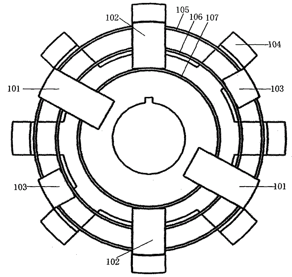
[0029] Such as image 3 , Figure 4 As shown, a three-phase U-shaped stator tooth external rotor switched reluctance motor includes a first stator (101), a second stator (102), a third stator (103), a rotor (104) and a first winding ( 105), the second winding (106), the third winding (107), the first stator (101), the second stator (102), and the third stator (103) have 6 total, using three different sizes U-shaped teeth, 2 of each size stator teeth. The six stator teeth are uniformly arranged along the circumference of the motor in order of large, medium and small sizes, and the mutually independent stator teeth are connected to each other by a disc (108) with a rectangular slot made of non-ferromagnetic material. The position between them is fixed and fixed on the casing (112) of the motor; the disk (108) is connected to the motor shaft (109) through the bearing (110); the first winding (105), the second winding (106) , The third winding (107) is three annular coils of di...


PUM


Abstract

The invention discloses an outer rotor switch reluctance motor with three-phase U-shaped stator teeth and a driving method of the outer rotor switch reluctance motor with the three-phase U-shaped stator teeth. The motor comprises three different kinds of U-shaped stator teeth, three different annular windings and a finger-shaped rotor installed outside stator magnetic poles. The total number of the stator teeth is even times of three. The numbers of the stator teeth in all sizes are identical. U-shaped stators are sequentially and evenly arranged in the circumferential direction of the motor in an intersected mode according to the sizes, and the stators mutually independent are fixed to an outer shell of a generator. The rotor is arranged outside the circumferences of the stators and provided with no brush, no winding and no permanent magnet. The three windings of the motor are wound in tooth grooves of the three different kinds of U-shaped stator teeth. The switch reluctance motor is simple in structure, corresponding driving circuits are simple, few switch components are used for the motor, control is easy, the cost for the motor and a power converter is low, winding of the windings is convenient, increasing of the number of the stator magnetic poles and rotor magnetic poles of the motor will not affect the winding space of the windings, and the outer rotor switch reluctance motor is more suitable for being applied at a low rotation speed.

Description

technical field [0001] The invention relates to a switched reluctance motor and a driving method thereof, in particular to a novel outer rotor switched reluctance motor using three different sizes of U-shaped stator teeth and a corresponding driving method thereof. Background technique [0002] The switched reluctance motor adopts a double salient pole iron core structure, and there are no brushes, no windings, and no permanent magnets on the rotor. It has the advantages of simple structure, firmness, reliable operation, high efficiency, and large starting torque. With the increasing development of national economic construction, the degree of mechanization and automation of all walks of life is getting higher and higher. Switched reluctance motors have huge potential markets in the fields of household appliances, aviation, aerospace, electronics, machinery and electric vehicles. The traditional switched reluctance motor has concentrated windings on each stator pole, and the...

Claims


Application Information

Patent Timeline
Patent Type & Authority Patents(China)
IPC IPC(8): H02K29/00H02K29/06H02P6/08H02P6/22
Inventor 冬雷
Owner 冬雷
Why Eureka
Try Eureka