An electric turning mechanism

A flipping mechanism, electric technology, applied in assembly machines, metal processing, metal processing equipment, etc., can solve the problems of restricting assembly quality and production efficiency, high energy consumption of hydraulic components, and large equipment space, and achieve the Small change, optimized force performance, stable change effect

Active Publication Date: 2016-05-25
安徽唐古拉工业技术有限公司
View PDF9 Cites 0 Cited by
  • Summary
  • Abstract
  • Description
  • Claims
  • Application Information

AI Technical Summary

Problems solved by technology

At present, hydraulically driven turning equipment is generally used. During the turning process, inertia will cause greater impact and instability. The turning process is difficult to control, and there are great potential safety hazards in production. Moreover, the equipment occupies a large space and the energy consumption of hydraulic components is high. High, frequent maintenance, seriously restricting the improvement of assembly quality and production efficiency

Method used


Image

  • An electric turning mechanism
  • An electric turning mechanism
  • An electric turning mechanism

Examples


Embodiment Construction

[0040] The principles and features of the present invention are described below in conjunction with the accompanying drawings, and the examples given are only used to explain the present invention, and are not intended to limit the scope of the present invention.

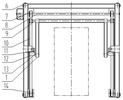
[0041] Such as figure 1 and 3 As shown, except for the reduction motor 5, all other devices are arranged symmetrically along the center line of the bottom edge of the U-shaped installation frame, wherein:

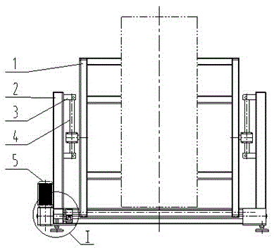
[0042] Such as figure 1 As shown, in a preferred embodiment of the present invention, the shown electric turning mechanism includes a fixed and turning workpiece 15 (such as Figure 4 As shown), the flip frame 1, the U-shaped mounting frame 2, the vertical guide rod 4 fixed on the U-shaped mounting frame 2 through the guide rod seat 3 and the outside of the U-shaped mounting frame 2 And be positioned at the deceleration motor 5 of any one in two vertices.

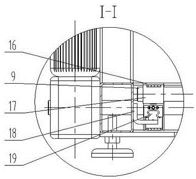
[0043] Such as figure 2 As shown, in another prefe...


PUM


Abstract

The invention provides an electric overturning mechanism. The electric overturning mechanism comprises a U-shaped mounting rack, a speed reduction motor arranged on the outer side of the U-shaped mounting rack and positioned in any one of two top angle ends, and a motor driving shaft connected with the speed reduction motor, wherein other devices are symmetrically arranged along the center line of the bottom side of the U-shaped mounting rack, the devices on any side of the center line of the bottom side comprise a pair of synchronous pulleys, a synchronous belt arranged on the synchronous pulleys, a movable overturning fixing block connected with the synchronous belt, an overturning driving shaft and an overturning driven shaft, one of the synchronous pulleys is arranged at one end of the motor driving shaft and can synchronously move with the motor driving shaft, the other one of the synchronous pulleys is positioned at the top end of the U-shaped mounting rack, one end of the overturning driving shaft penetrates into the movable overturning fixing block and the other end of the overturning driving shaft is fixed with an overturning rack which is used for fixing and overturning a workpiece, and the overturning driven shaft is fixed with the overturning rack and can move up and down. The electric overturning mechanism can save the site area, does less work, and has low energy consumption, simple structure, convenience in maintenance and safety and reliability.

Description

technical field [0001] The invention relates to the field of assembly technology. Specifically, the present invention relates to an electric overturning mechanism used for 90-degree overturning of large cabinet parts when required by the process. Background technique [0002] The heavy equipment manufacturing industry is the top priority of the equipment manufacturing industry. It is an industry related to national economic development and security. It is the basis for the development of cutting-edge products in the fields of national defense, military industry, aviation, and aerospace. The ability is the key to realizing my country's progress from a manufacturing power to a manufacturing power. [0003] Large-sized and heavy-weight workpieces in heavy equipment manufacturing generally need to be turned over many times during their manufacturing and assembly process. At present, hydraulically driven turning equipment is generally used. During the turning process, inertia wi...

Claims


Application Information

Patent Timeline
Patent Type & Authority Patents(China)
IPC IPC(8): B23P19/00
CPCB23P21/002
Inventor 张彦海俞锋陈婷婷
Owner 安徽唐古拉工业技术有限公司
Why Eureka
Try Eureka