A cathode device for a vacuum coating production line

A technology of vacuum coating and production line, applied in vacuum evaporation coating, sputtering coating, ion implantation coating, etc. Low material utilization rate and other issues, to achieve the best coating stability and uniformity, simple structure, and improve the effect of utilization

Active Publication Date: 2016-03-09
XIANGTAN HONGDA VACUUM TECH CO LTD
View PDF8 Cites 0 Cited by
  • Summary
  • Abstract
  • Description
  • Claims
  • Application Information

AI Technical Summary

Problems solved by technology

However, the cathode device is affected by its own dimensional accuracy and strong magnetic attraction, especially during installation, the assembly accuracy is difficult to meet the design accuracy requirements
Chinese patent CN201778106U discloses a rectangular planar magnetron cathode structure in vacuum coating equipment. This cathode structure solves the above problems to a certain extent, but its target utilization rate still cannot achieve a qualitative leap
Chinese patent CN201770767U discloses a vacuum coating cathode device. The main technical problem solved by this patent is to simplify the process of replacing the target, save the time required for replacing the target, and does not solve the technical problem of low target utilization.

Method used


Image

  • A cathode device for a vacuum coating production line
  • A cathode device for a vacuum coating production line
  • A cathode device for a vacuum coating production line

Examples


Embodiment Construction

[0035] The present invention will be further described in detail and completely below in conjunction with the embodiments and the accompanying drawings.

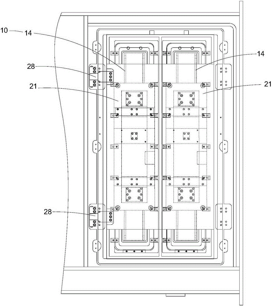
[0036] Figure 3-6 It is a schematic structural diagram of a cathode device for a vacuum coating production line provided by the present invention. in, image 3 A schematic diagram of the assembly of the cathode device, such as image 3 As shown, the cathode device includes: a cathode assembly 10 and a translation assembly 20, the cathode assembly 10 is fixedly connected to the translation assembly 20 and moves in translation with the movement of the translation assembly 20, wherein the cathode is a planar magnetron sputtering cathode. The cathode assembly and the translation assembly pass through An insulator 30 is connected.

[0037] Figure 4 The top sectional view of the cathode device for the vacuum coating production line provided by the present invention; Figure 5 It is a left sectional view of a cathode device ...


PUM


Abstract

The invention discloses a cathode device for a vacuum coating production line, comprising a cathode assembly and a translation assembly, the cathode assembly is fixedly connected to the translation assembly and moves in translation with the movement of the translation assembly, wherein the cathode in the cathode assembly is a plane Magnetron sputtering cathode. Compared with the prior art, the cathode device provided by the present invention can not only maintain the advantages of low cost and easy maintenance of the planar cathode, but also realize the advantages of variable target and bombardment orbit of the rotating cathode, and realize the additional components of translation The structure is simple, it will not affect the vacuum sealing, and it will not become an uncertain factor in the production line; therefore, the cathode device has great economic value, is environmentally friendly, and reduces the waste of the target, so its application prospect is very good broad.

Description

technical field [0001] The invention relates to the technical field of a vacuum coating production line, in particular to a cathode device for a vacuum coating production line. Background technique [0002] Vacuum coating is a technology that prepares a film layer in a vacuum to produce a thin film material. Specifically, the atoms of the material in the vacuum chamber are separated from the heating source and hit the surface of the object to be plated, including plated crystalline metals, semiconductors, and insulators. Elemental or compound membranes. Although chemical vapor deposition also uses vacuum methods such as decompression, low pressure or plasma, vacuum coating generally refers to the deposition of thin films by physical methods. There are three forms of vacuum coating, namely evaporation coating, sputtering coating and ion plating. [0003] Sputtering coating is the most important method in vacuum coating. This technology uses energetic particles to bombard th...

Claims


Application Information

Patent Timeline
Patent Type & Authority Patents(China)
IPC IPC(8): C23C14/35
Inventor 黄国兴孙桂红祝海生黄乐梁红吴永光
Owner XIANGTAN HONGDA VACUUM TECH CO LTD
Why Eureka
Try Eureka