Drying, dehydrating and dehumidifying device
A drying and cabinet technology, applied in the direction of drying gas arrangement, local stirring dryer, static material dryer, etc., can solve the problems of environmental pollution, waste of heat energy, limit the temperature and air volume of recovered waste heat, and reduce environmental pollution. , to achieve the effect of recycling
- Summary
- Abstract
- Description
- Claims
- Application Information
AI Technical Summary
Problems solved by technology
Method used
Image

Examples
Embodiment 1
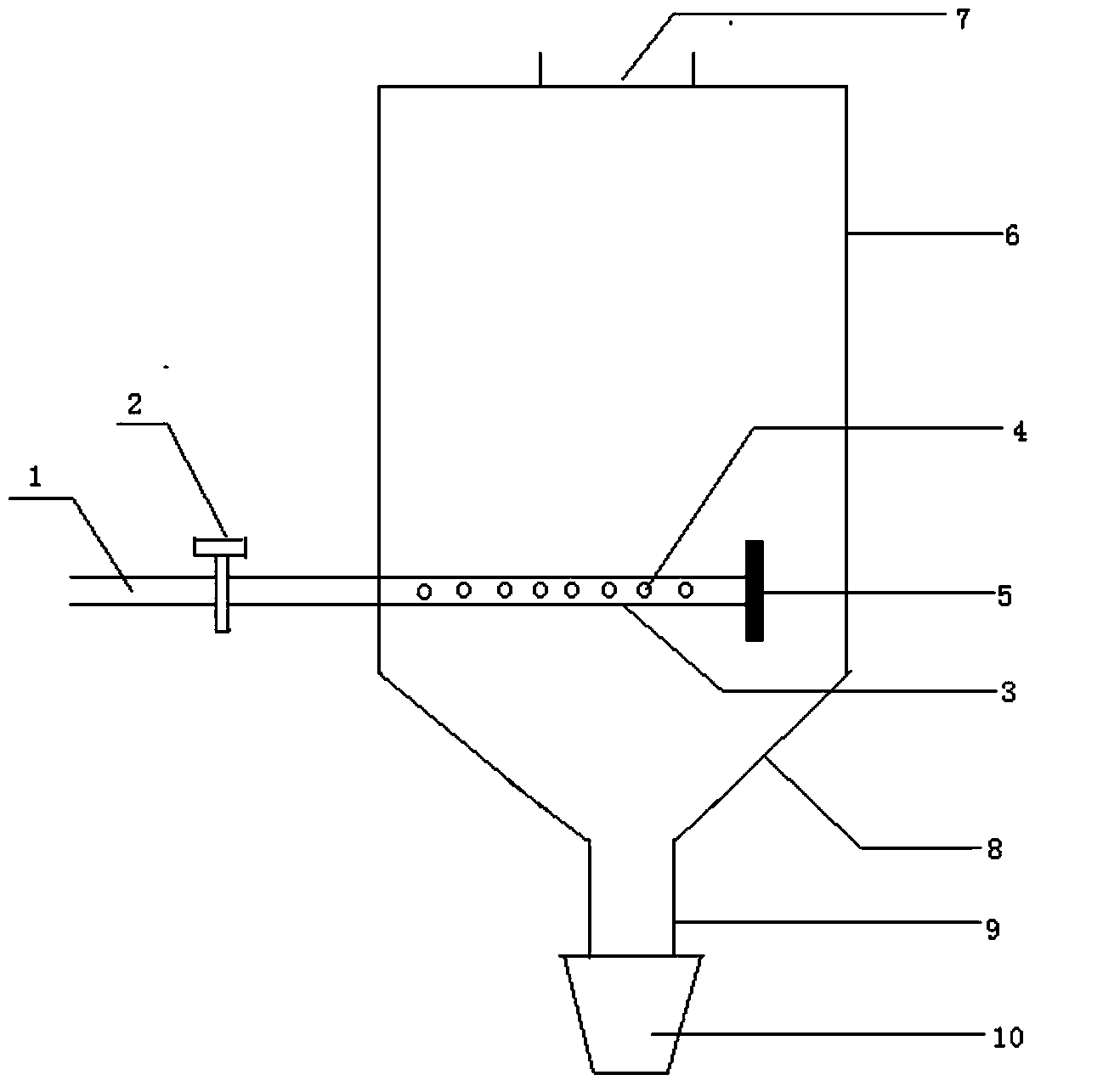
[0014] A dry dehydration and dehumidification device is composed of an air inlet pipe 1, an air regulating valve 2, a dehydration and dehumidification pipe 3, and a box body 6. The dehydration and dehumidification pipe 3 is connected with the air inlet pipe 1 through the air regulating valve 2, and the other end of the dehydration and dehumidification pipe 3 There is a blind plate 5, the surface of the dehydration and dehumidification pipe 3 is evenly covered with holes 4, the diameter of the hole 4 is 3mm, the top of the box body 6 has a feed port 7, and the bottom has a hopper 8, and the end of the hopper 8 is a discharge port 9. The feeding port 9 is provided with a screw pusher 10 .
Embodiment 2
[0016] Same as embodiment 1, the difference is that the diameter of the hole 4 is 4mm, and the discharger 10 is a common discharger.
PUM
| Property | Measurement | Unit |
|---|---|---|
| Aperture | aaaaa | aaaaa |
| Aperture | aaaaa | aaaaa |
Abstract
Description
Claims
Application Information