
A speed sensor signal inspection device

A technology of speed sensor and inspection device, which is applied to measuring devices, instruments, speed/acceleration/shock measurement, etc., which can solve the problems of not being able to know the working status of the probe, low frequency of hand shaking, and personnel fatigue, and achieve quick disassembly and adjustment Distance, easy to adjust the distance, to ensure the effect of complete recording

Active Publication Date: 2017-02-15
STATE GRID CORP OF CHINA +1
View PDF6 Cites 0 Cited by
  • Summary
  • Abstract
  • Description
  • Claims
  • Application Information

AI Technical Summary

Problems solved by technology

At this stage, the inspection of photoelectric sensors is to use the method of shaking the reflective tape by hand. This method is very clumsy and easy to cause fatigue, and the frequency of hand shaking is low and often cannot be recognized by the probe, and it is impossible to know the speed of the probe at high speed. working status
There have been situations where it works normally at low speeds and has no readings at high speeds
For eddy current sensors, there is no good method, just to measure whether there is voltage transmitted back from the probe.

Method used


Image

  • A speed sensor signal inspection device
  • A speed sensor signal inspection device

Examples


Embodiment Construction

[0020] The implementation of the present invention will be described in further detail below in conjunction with the accompanying drawings. The following embodiments are only descriptive, not restrictive, and cannot limit the protection scope of the present invention.

[0021] Invention idea

[0022] The basic principle of the invention is to simulate the rotation of the rotating shaft of the rotating machine, and trigger the sensor with the real physical rotational speed to check whether the signal channel is smooth or not and the working stability of the device.

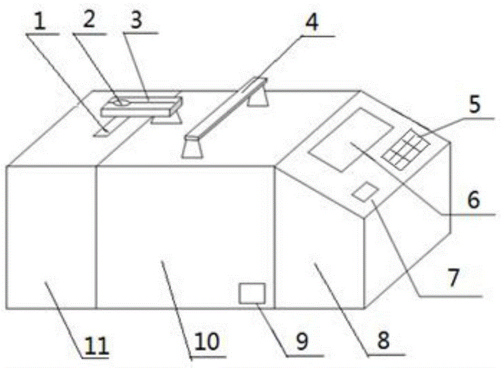
[0023] A speed sensor signal inspection device, such as figure 1 As shown, the device housing is included, and the housing is divided into a left housing 11, a middle housing 10 and a right housing 8, and a handle 4 is installed on the upper surface of the middle housing to facilitate the movement of the device. A power socket 9 is fixedly installed on the front side wall of the middle part housing, a display scre...


PUM


Abstract

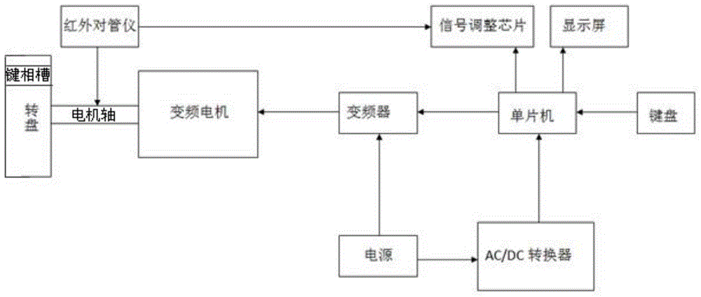
The invention relates to a rotation speed sensor signal detection device, which comprises a handle, a power supply socket, a display screen, a button switch, a keyboard, a strip-shaped through hole and a sensor clip above the strip-shaped through hole which are arranged on the surface of the shell. The device also comprises a variable-frequency motor, a frequency converter, a single chip microcomputer, a signal adjusting chip, an infrared emitting diode and photodiode speed meter, an alternating current power supply and an AC / DC converter which are arranged inside the shell. A turntable is coaxially arranged on the left end head of the motor shaft; and the edge of the turntable is provided with an axial key phase groove. The invention creates a brand-new rotation speed sensor signal detection method, one hundred percent safe detection on the sensor can be realized in a physical quantity analog method, detection on working conditions of the sensor in different rotation speeds can be realized, the detection range is expanded, the detection ability is improved, and the detection data can be ensured to be fully and completely recorded.

Description

technical field [0001] The invention belongs to the technical field of power system sensor signal inspection, in particular to a speed sensor signal inspection device. Background technique [0002] Vibration and speed signals need to be connected when performing vibration monitoring tests on rotating machinery. Among them, the vibration signal is used to record the vibration amplitude of each bearing and each part of the unit on the time axis; the speed signal is used to record the rotation speed of the unit on the time axis, and the data acquisition and analysis equipment can compare the two to calculate and draw the vibration and speed It is very important and critical for vibration fault analysis and diagnosis. Most of the vibration monitoring tests are carried out for the start-up process of the unit. It is necessary to install vibration and speed sensors on the equipment when the unit is shut down, and start the test before starting to monitor and record the vibration ...

Claims


Application Information

Patent Timeline
Patent Type & Authority Patents(China)
IPC IPC(8): G01P21/02
Inventor 屈斌张宁甘智勇张利王建王梓越
Owner STATE GRID CORP OF CHINA
Learn More