
Heating equipment and heating method

A technology of heating equipment and heating section, applied in heat treatment equipment, induction heating, electric/magnetic/electromagnetic heating, etc., can solve the problems of coil cooling water leakage, difficulty in manufacturing coils, complicated system, etc., to achieve overheating and simple structure Effect

Inactive Publication Date: 2016-02-24
POHANG IRON & STEEL CO LTD
View PDF6 Cites 0 Cited by
  • Summary
  • Abstract
  • Description
  • Claims
  • Application Information

AI Technical Summary

Problems solved by technology

In addition, the section or shape of the heating coil changes at the top, so the coil needs to be manufactured by welding, and it is possible to form a hole in the welded part due to overheating, thereby causing leakage of coil cooling water based on the hole
That is, in this case, there are disadvantages such as difficulty in manufacturing the coil, complicated system, and high initial investment cost.

Method used


Image

  • Heating equipment and heating method
  • Heating equipment and heating method
  • Heating equipment and heating method

Examples


Embodiment Construction

[0058] Next, specific embodiments of the present invention will be described with reference to the drawings.

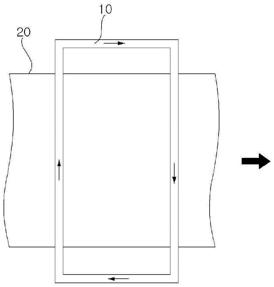
[0059] Figure 5a is a graph showing the eddy current density profile when heated with the TFIC in FIG. 3; Figure 5b is shown in Figure 5a Diagram of the induced eddy current path in the metal plate of . As shown in FIG. 5 , when the TFIC in FIG. 3 is used, it can be seen that eddy currents are concentrated at the edge portion E. As shown in FIG. This is because the magnetic field is distorted and concentrated in the edge portion E, thereby causing an end effect (Endeffect) in which the eddy current density increases.

[0060] The end effect is generated not only at the edge portion E inside the heating coil, but also at the edge portion E’ outside the heating coil, therefore, as Figure 5b As shown, the eddy current loop (Loop) will form an outer current loop in addition to the main current path in the middle part. Eventually, a point where the current splits ...


PUM

PropertyMeasurementUnit
penetration depthaaaaaaaaaa
diameteraaaaaaaaaa
thicknessaaaaaaaaaa

Abstract

The present invention provides a heating device, which has a simple coil structure and can realize overheating of an edge portion of a metal plate and uniform heating of the metal plate in a width direction, the heating device includes: a first heating part, one surface of the metal plate is spaced to generate a magnetic field for heating the metal plate, and is disposed parallel to the metal plate; and a second heating portion is spaced from the other surface of the metal plate, wherein the first and the second heating portion each include a magnetic core extending along a lateral portion of the wound coil extending in the moving direction / width direction of the metal plate, the magnetic core having a lateral portion along the wound coil The inner side surface of the first member extends, and the outer side surface of the transverse portion in the winding coil is open.

Description

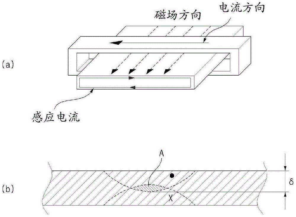
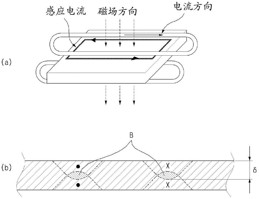
technical field [0001] The present invention relates to a heating device and a heating method, and more particularly to a heating device for heating a continuously supplied metal plate and uniformly heating a portion other than the edge portion while overheating the edge portion and heating method. Background technique [0002] Transverse Flux Induction Coil (Transverse Flux Induction Coil, called "TFIC") is developed from Longitudinal Flux Induction Coil (called "LFIC"), which belongs to one of the induction heating technologies. [0003] exist figure 1 , the principle of heating a metal plate by LFIC is shown. [0004] That is, if figure 1 As shown in (a), the magnetic field generated by the LFIC acts on the metal plate in the longitudinal direction, thereby generating an eddy current (Eddycurrent) on the vertical section of the metal plate. In order to efficiently perform the heating of the metal plate based on the eddy current, the thickness of the metal plate should...

Claims


Application Information

Patent Timeline
Patent Type & Authority Patents(China)
IPC IPC(8): H05B6/02
CPCC21D1/10C21D1/42C21D9/60H05B6/101H05B6/104H05B6/362H05B6/365H05B6/40H05B6/42H05B6/44Y02P10/25H05B6/02
Inventor 朴钟守裴振秀河泰宗赵云宽申健吴基庄李德万
Owner POHANG IRON & STEEL CO LTD
Learn More