
Airport de-icing equipment

A technology for anti-icing equipment and airports, applied to aircraft parts, ground equipment, spraying vehicles, etc., can solve the problems of high heating power, unstable temperature control, and long time, so as to increase the base temperature, save heating time, and stabilize good sex effect

Active Publication Date: 2016-03-23
SHANDONG TAIKOO AIRCRAFT ENG
View PDF6 Cites 0 Cited by
  • Summary
  • Abstract
  • Description
  • Claims
  • Application Information

AI Technical Summary

Problems solved by technology

However, the difficulty of deicing is determined by the large size of the aircraft and the complexity of the structure.
[0006] After analysis, a large part of the flight delays in winter is caused by the inability to complete the de-icing work of the aircraft in time, because the de-icing fluid must be heated to a certain temperature (about 85°C) and then sprayed on the surface of the ice and snow to play a corresponding role. Some of the existing deicing and anti-icing equipment are preheating type, and the heating power is relatively large. It takes a very long time to heat up another box of deicing fluid after a box of deicing fluid is used up, which is difficult to meet the requirements of continuous deicing for a long time.
However, other equipment with instant heating devices have problems such as unstable temperature control, large system pressure loss, and insufficient reliability of the overall equipment. The existing deicing and anti-icing facilities can no longer meet the requirements of civil aviation airports in winter.
[0007] In addition, ice and snow removal work in important areas of the airport is also a thorny problem that airports in the north often face. The failure to clear ice and snow from aircraft taxiways and runways in time is also an important factor leading to flight delays.

Method used


Image

  • Airport de-icing equipment
  • Airport de-icing equipment
  • Airport de-icing equipment

Examples


Embodiment Construction

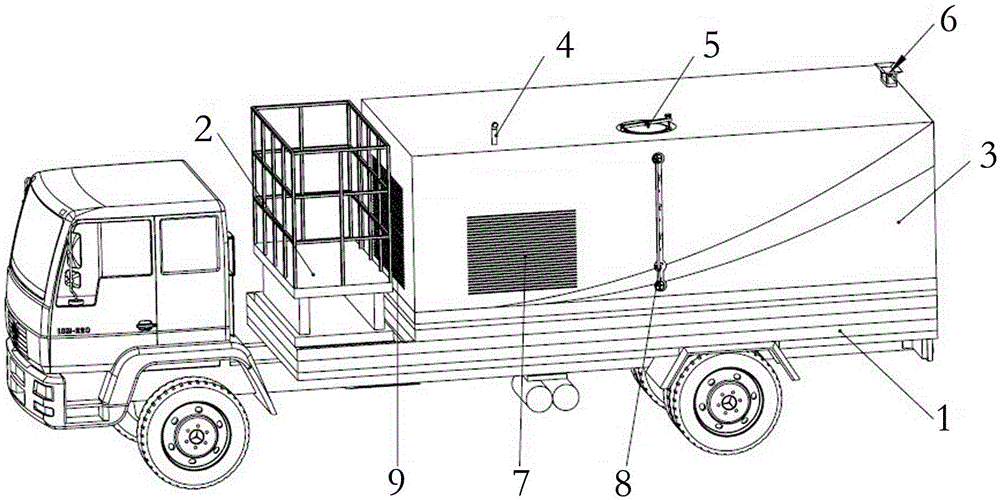
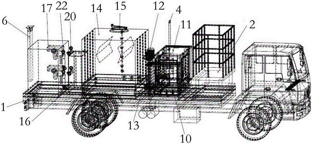
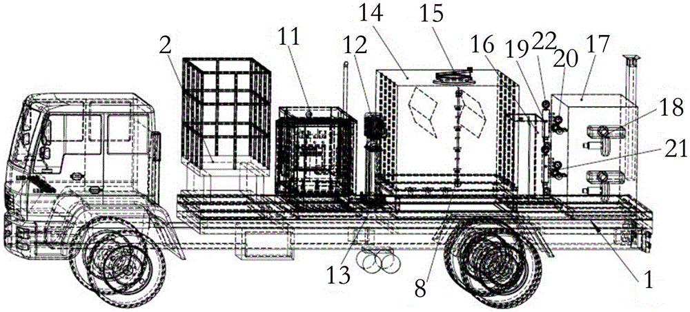
[0032] Refer to the attached Figures 1 to 5 , is an embodiment of a better-configured airport deicing and anti-icing equipment, which adopts a general-purpose automobile chassis 1, and of course, it can also be modified to adapt to the special application of the deicing and anti-icing equipment.

[0033] Such as Figure 1-5 Deicing and anti-icing equipment shown, the body of which consists of:

[0034] General Motors Chassis 1 (hereinafter referred to as the chassis), the wheeled chassis is shown in the figure, and the wheeled chassis has fast speed and low noise.

[0035] Compared with the GM chassis 1, some modification is carried out, and an automobile engine power take-off is added, or an engine is installed. The engine outputs two transmission shafts, one of which is connected to the original automobile transmission rod, and is passed through the transmission of the automobile. The system drives the car to run normally; the other shaft is connected to the input shaft o...


PUM


Abstract

The invention discloses an ice removing and preventing device of an airport. The ice removing and preventing device comprises a chassis, an ice removing and preventing liquid tank, a coil furnace, spray devices and a lifting platform. The chassis is used as a vehicle and can move; the ice removing and preventing liquid tank is mounted on the chassis and is used for providing ice removing liquid; the coil furnace is mounted on the chassis, liquid inlets of the coil furnace are connected with the ice removing and preventing liquid tank, the liquid is outputted via two parallel pipelines, and liquid which flows in one of the pipelines can flow back to the ice removing and preventing liquid tank; the spray devices are connected with the other pipeline of the coil pipe; the lifting platform is mounted on the chassis, and operators can carry out spray operation on the lifting platform. The ice removing and preventing device has the advantages that the ice removing and preventing device can continuously work for a long time, and accordingly ground service requirements of airline companies and corporate customers of the airport can be met.

Description

technical field [0001] The invention relates to an airport deicing and anti-icing equipment. Background technique [0002] With the development of the aviation industry, aircraft deicing equipment has a history of nearly a hundred years. The early aircraft deicing method was relatively primitive. People stood on ladders or brackets and used hot water pipes to remove the frozen parts of the aircraft body. . As the airframe becomes larger and larger, this deicing method is inefficient and cannot meet the normal operating requirements of airlines. Specialized deicing vehicles were first produced in high-latitude Nordic countries, such as Denmark and Sweden, where the winter is long and aircraft icing is prominent. [0003] When an aircraft encounters cold weather such as low temperature, high humidity, rainfall, and snowfall, a layer of frost, snow, or ice will form on its surface. Ice and snow condense on the wings of the aircraft, which will make the surface of the wings r...

Claims


Application Information

Patent Timeline
Patent Type & Authority Patents(China)
IPC IPC(8): B64F1/36B60P3/30E01H10/00B64F5/23
Inventor 张云鹏
Owner SHANDONG TAIKOO AIRCRAFT ENG
Learn More