Connecting mechanism of oil well pump delivery valve
A connection mechanism, oil outlet valve technology, applied in the direction of parts, pump elements, mechanical equipment, etc. of pumping devices for elastic fluids
- Summary
- Abstract
- Description
- Claims
- Application Information
AI Technical Summary
Problems solved by technology
Method used
Image
Examples
Embodiment 1
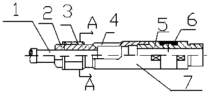
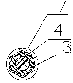
[0020] Such as Figure 1-2 As shown, the present invention includes an oil sucking rod 1, a pressure cap 2, a fixed nut 3, a hexagonal fixed sleeve 4 and an oil outlet valve 7, the small end of the oil outlet valve 7 is covered with a hexagonal fixed sleeve 4, and the hexagonal fixed sleeve 4 can Slide left and right; one end of the oil pump rod 1 is sequentially covered with a fixed nut 3 and a pressure cap 2, which is located between the pressure cap 2 and the hexagonal fixed sleeve 4, the pressure cap 2 is milled into a hexagonal shape, and one end of the fixed nut 3 is The car has an annular groove, which is welded on the oil sucking rod 1 as a welding cavity. The inside and outside of the hexagonal fixing sleeve 4 are hexagonally milled, and the small end of the oil outlet valve 7 and the fixing nut 3 are located in the hexagonal fixing sleeve 4. .
[0021] When connecting, first screw the pressure cap into the oil sucker rod, then install the lock nut and adjust it to t...
Embodiment 2
[0023] The preferred specific structure of this embodiment on the basis of Embodiment 1 is as follows: the outer surface of the small end of the oil delivery valve 7 is a hexagonal structure, the outer hexagonal structure of the small end of the oil delivery valve 7, the outer hexagonal structure of the fixing nut 3 and the hexagonal structure inside the hexagonal fixing sleeve 4 The structures are of equal size. It is convenient to snap both the fixing nut and the oil outlet valve into the hexagonal fixing sleeve.
Embodiment 3
[0025] This embodiment adds the following technical features on the basis of the above embodiments: the oil outlet valve 7 is also provided with a movable joint 5 .
[0026] The movable joint 5 includes left and right joints and a collar 6 connected between the left and right joints. After the coupling connects the left and right joints, the left and right joints can rotate freely. When the plunger is stuck with the pump barrel, it cannot rotate freely, but the movable joint can rotate freely, so as to ensure the effective connection of the thread and prevent the loosening of the sucker rod and the oil delivery valve. The structure is simple, reliable, reliable without change, does not change the parameters of the working structure, does not affect the work, can be disassembled repeatedly, is easy to process and manufacture, and is convenient for on-site assembly.
[0027] The outer surface of the sucker rod 1 is provided with threads.
[0028] One end of the hexagonal fixin...
PUM
 Abstract
Description
Claims
Application Information
 - R&D
- Intellectual Property
- Life Sciences
- Materials
- Tech Scout
- Unparalleled Data Quality
- Higher Quality Content
- 60% Fewer Hallucinations
Browse by: Latest US Patents, China's latest patents, Technical Efficacy Thesaurus, Application Domain, Technology Topic, Popular Technical Reports.
© 2025 PatSnap. All rights reserved.Legal|Privacy policy|Modern Slavery Act Transparency Statement|Sitemap|About US| Contact US: help@patsnap.com


