Controllable hot air distributor and grain drying equipment with same

A hot air arrangement and grain technology, applied in lighting and heating equipment, drying gas arrangement, and preservation of seeds through drying, etc., can solve the problems of reduced contact time between grain and hot air, not the largest contact area, and uneven airflow pressure. Achieve good drying effect, reduce occupied volume and high drying efficiency

Active Publication Date: 2014-09-10
SHANGHAI FORWARD MASCH CO LTD
View PDF9 Cites 2 Cited by
  • Summary
  • Abstract
  • Description
  • Claims
  • Application Information

AI Technical Summary

Problems solved by technology

However, hole-shaped air outlets are used on the punching plate, and the sizes of the air outlets in different areas are different, resulting in uneven airflow pressure and high energy consumption. The grains are elliptical, and there is a certain distance between the air outlets. The airflow may pass between the two grains without causing the grains to rise or jump. The contact time between the grains and the hot air is reduced, and the contact area is not the largest. , so that the drying efficiency is reduced

Method used


Image

  • Controllable hot air distributor and grain drying equipment with same
  • Controllable hot air distributor and grain drying equipment with same
  • Controllable hot air distributor and grain drying equipment with same

Examples


Embodiment Construction

[0030] In order to make the technical means, creative features, goals and effects achieved by the present invention easy to understand, the specific implementation methods provided by the present invention will be described in detail below in conjunction with the accompanying drawings; this embodiment is implemented on the premise of the technical solution of the present invention. The detailed implementation and process are given, but the protection scope of the present invention is not limited to the following examples.

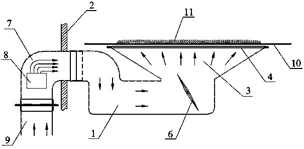
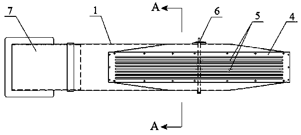
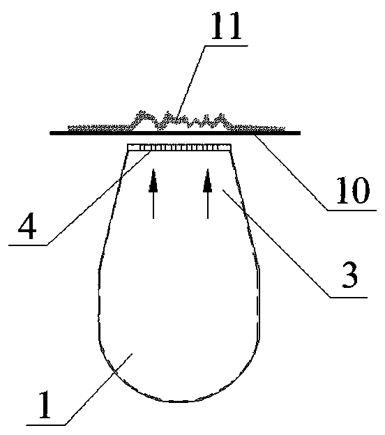
[0031] Please refer to figure 1 , the arrow in the figure shows the air flow direction, the controllable hot air arrangement device includes an air supply mechanism and a heating mechanism, the air supply mechanism includes a fan and a driving motor (not shown in the figure), the heating mechanism includes a heating air pipe 7 and is set on the heating The heater 8 inside the air duct 7 can be a mid-wave infrared heating tube, which can heat the passing air...


PUM


Abstract

The invention discloses a controllable hot air distributor which comprises an air supply mechanism and a heating mechanism. The heating mechanism is provided with a heater in a heating air pipe, one end of the heating air pipe is connected with an air supply opening of a fan of the air supply mechanism, the other end of the heating air pipe is connected with an S-shaped air flue, the S-shaped air flue is fixedly arranged on the inner side of a closed box, an air outlet of the S-shaped air flue is upward, an air distribution plate is fixedly arranged on the air outlet, a plurality of strip-shaped through holes are formed in the air distribution plate, the section of the air outlet of the S-shaped air flue in the direction perpendicular to the grain conveying direction is in a horn shape, the section of the air outlet of the S-shaped air flue in the direction parallel to the grain conveying direction is narrow in upper portion and wide in lower portion, and a butterfly valve for adjusting the direction and flow of hot air is arranged below the air outlet of the S-shaped air flue. The S-shaped air flue is adopted to enable airflow to pass through the air outlet from bottom to top, air resistance is lowered, the hot air passes through the strip-shaped through holes formed in the air distribution plate to form the wall-shaped airflow, grain can bounce evenly and continuously when flowing on a net belt, and the contact time and contact area of the grain and the hot air are increased.

Description

technical field [0001] The invention relates to the technical field of grain drying devices, in particular to a controllable hot air arranger and grain drying equipment using the same. Background technique [0002] After harvesting, the grain needs to be stored in storage according to a certain standard moisture content. The traditional operation method is to reduce the moisture content by drying and natural ventilation. The research on foreign grain drying machinery started in the 1940s, and developed rapidly and more perfect in the later period. Most of the drying devices adopt high-temperature drying methods, such as the United States, Japan, and the former Soviet Union, which use diesel oil and liquefied gas as heat sources for direct drying. Domestic research on grain drying machinery started relatively late, and in terms of heat sources, straw combustion, gas, generators, etc. were added, and drying equipment gradually adapted to regional characteristics. At this stage...

Claims


Application Information

Patent Timeline
Patent Type & Authority Applications(China)
IPC IPC(8): F26B21/00A23B9/08
Inventor 魏金富
Owner SHANGHAI FORWARD MASCH CO LTD
Why Eureka
Try Eureka