Laboratory microwave deicing instrument

A laboratory, microwave technology, applied in the direction of material analysis, instruments, and scientific instruments using microwave means, can solve the problem of no microwave deicing experimental instruments, etc., and achieve the effect of simple structure and small volume

Inactive Publication Date: 2014-09-10
HEILONGJIANG INST OF TECH
View PDF8 Cites 2 Cited by
  • Summary
  • Abstract
  • Description
  • Claims
  • Application Information

AI Technical Summary

Problems solved by technology

[0003] The present invention is to solve the problem that there is no microwave deicing experiment

Method used


Image

  • Laboratory microwave deicing instrument
  • Laboratory microwave deicing instrument
  • Laboratory microwave deicing instrument

Examples


specific Embodiment approach 1

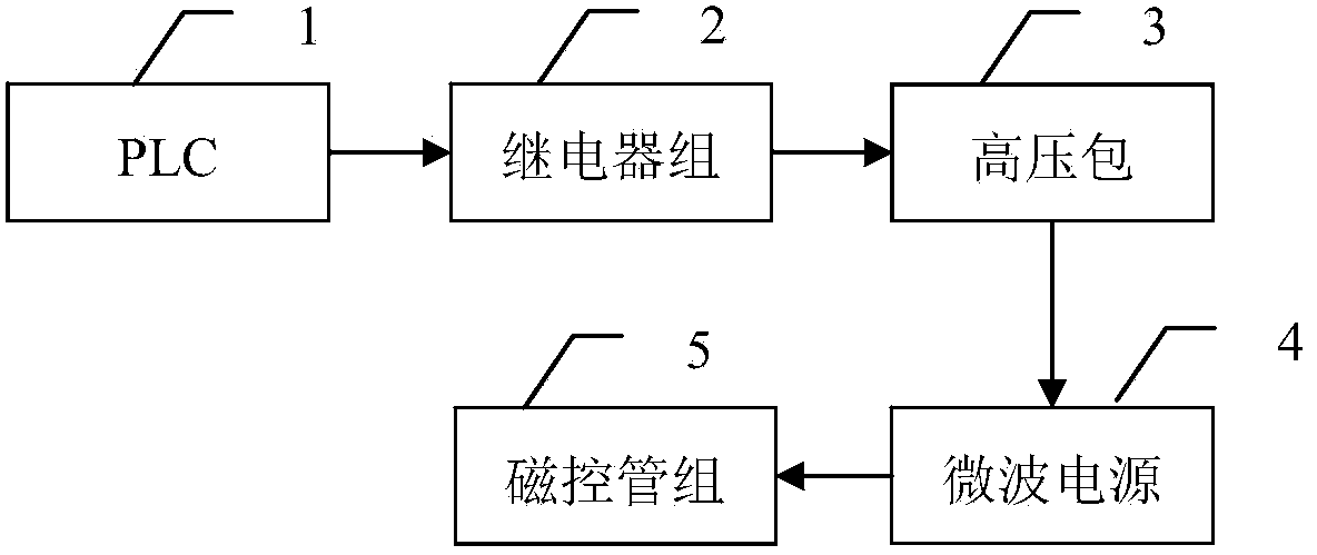
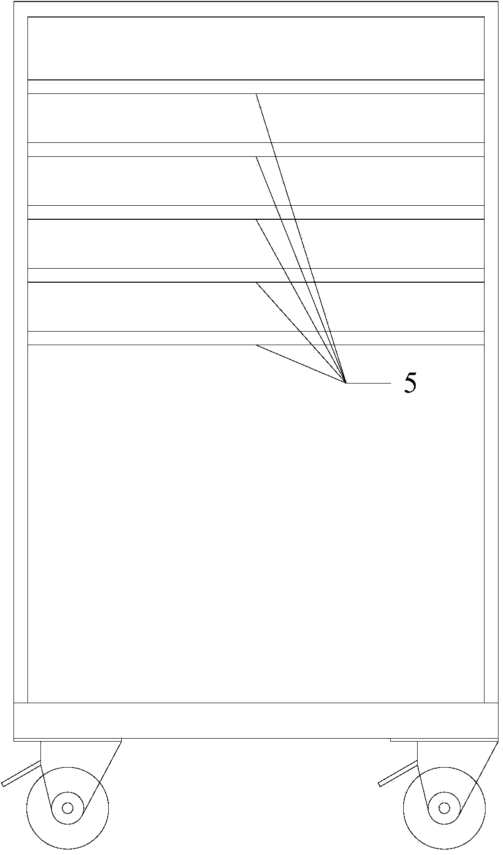
[0014] Specific implementation mode one: refer to figure 1 , figure 2 and image 3 Describe this embodiment in detail, the laboratory microwave deicer described in this embodiment, it comprises: PLC1, relay group 2, high voltage bag 3, microwave power supply 4, magnetron group 5, shell 6 and cavity door 7 ;

[0015] The current control signal output terminal of PLC1 is connected to the current control signal input terminal of relay group 2, the current signal output terminal of relay group 2 is connected to the current signal input terminal of high voltage package 3, and the voltage output terminal of high voltage package 3 is connected to the voltage input terminal of microwave power supply 4 terminal, the voltage output terminal of the microwave power supply 4 is connected to the voltage input terminal of the magnetron group 5;

[0016] A timing unit is embedded in PLC1;

[0017] The relay group 2 includes n relays, wherein n is a positive integer, the current control s...

specific Embodiment approach 2

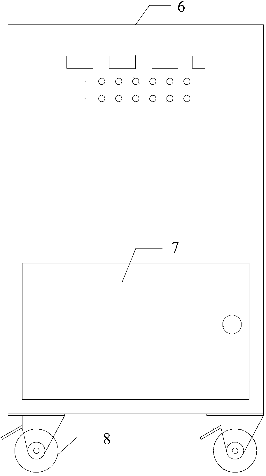
[0021] Specific embodiment 2: This embodiment is a further description of the laboratory microwave deicer described in specific embodiment 1. In this embodiment, it also includes: m rollers 8, wherein m is a positive integer; m The rollers 8 are all fixed on the bottom of the shell 6 .

[0022] In this embodiment, adding rollers to the bottom of the laboratory microwave deicer can make it easy to move and easy to operate.

specific Embodiment approach 3

[0023] Specific embodiment three: this embodiment is to further explain the laboratory microwave deicer described in specific embodiment one. In this embodiment, it also includes: n indicator lights; n indicator lights are respectively connected in series to n Between the magnetrons and the microwave power supply 4, there are n indicator light openings on the casing 6, and the n indicator lights correspond to the n indicator light openings one by one and are embedded in the indicator light openings.

[0024] In this embodiment, n indicator lights are respectively connected in series between the n magnetrons and the microwave power supply 4 , which can intuitively show whether each magnetron is powered on and working. However, when any one of the magnetrons is damaged, the fault point can be quickly found.


PUM


Abstract

The invention relates to a laboratory microwave deicing instrument, belonging to the field of microwave deicing. The laboratory microwave deicing instrument solves the problem that no microwave deicing instrument is arranged in the laboratory. A PLC (Programmable Logic Controller) is utilized to adjust the power of each magnetron by a relay, so that the power of a deicing instrument body is adjusted, wherein the maximum power can reach 10000w, and furthermore, the purpose of testing road surfaces with different materials can be achieved; the whole laboratory microwave deicing instrument is of a sealed structure and cannot cause microwave pollution; besides, the laboratory microwave deicing instrument has a simple structure and small volume and is suitable for laboratory operations.

Description

technical field [0001] The invention belongs to the field of microwave deicing. Background technique [0002] Ice accumulation on roads will bring inconvenience to road traffic, and in severe cases, it will endanger the lives of pedestrians. Effective deicing, especially for important facilities such as highways, bridges, and airport runways, has always been a common concern of countries located in high latitude regions of the world. Road microwave deicing, as a new environmentally friendly deicing method, has received widespread attention. When using microwave radiation to remove ice and snow, asphalt or cement pavement absorbs microwaves much better than ice, and microwaves can penetrate through the ice to heat the pavement. After the temperature of the pavement material rises, the heat is transferred to the ice layer, which makes the ice layer at the junction heat up and melt, and the adhesion between the ice layer and the road surface is reduced, so as to achieve the p...

Claims


Application Information

Patent Timeline
IPC IPC(8): G01N22/00
Inventor 孙凌于文勇张家平武鹤关辉贺东飚杨伟杰于文
Owner HEILONGJIANG INST OF TECH
Why Eureka
Try Eureka