Liquid crystal displaying panel
A liquid crystal display panel and substrate technology, applied in nonlinear optics, instruments, optics, etc., can solve the problems of display panel 12 corrosion, glue material leakage, isolation, etc., to improve production yield, maintain balance between internal and external air pressure, and avoid leaked effect
- Summary
- Abstract
- Description
- Claims
- Application Information
AI Technical Summary
Problems solved by technology
Method used
Image
Examples
Embodiment 1
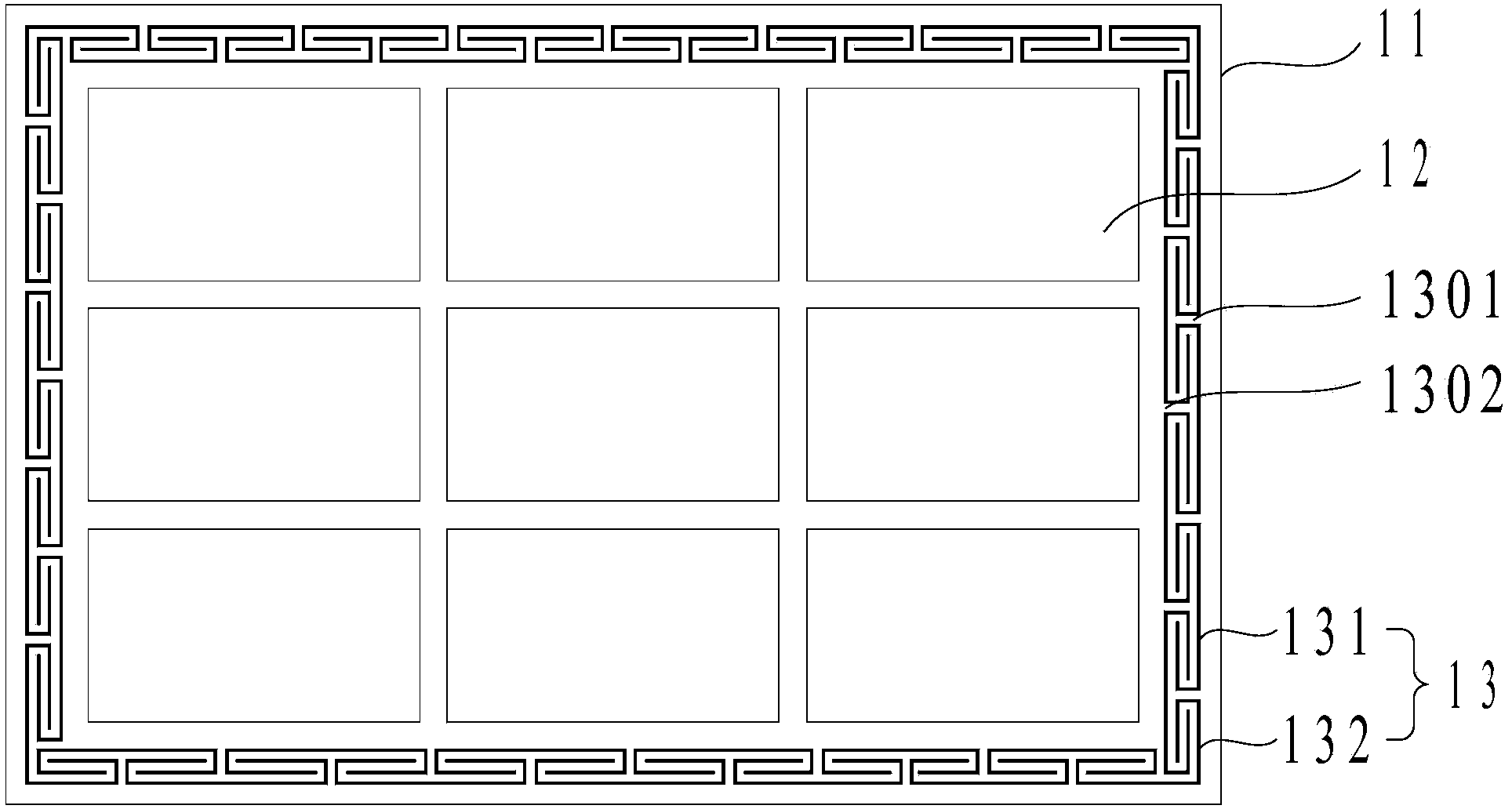
[0026] Please refer to Figure 2a , Figure 2a It is a schematic top view structural diagram of a liquid crystal display panel proposed in Embodiment 1 of the present invention.
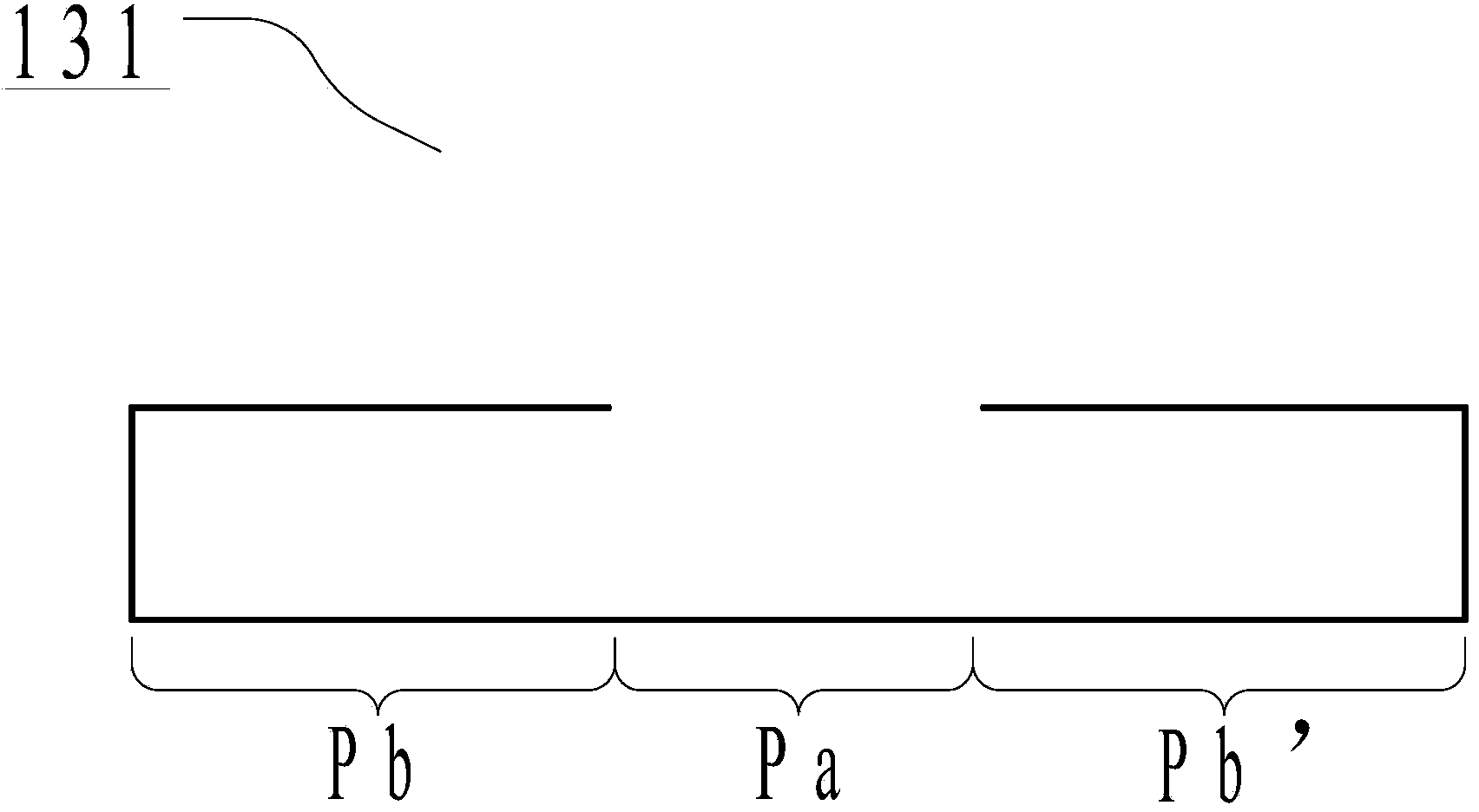
[0027] Such as Figure 2a As shown, the liquid crystal display panel includes: two oppositely arranged substrates 11, a sealant 13 disposed between the two substrates and located around the two substrates, the sealant includes a plurality of sealant units, the A plurality of sealant units include a connecting section and end structures located at both ends of the connecting section, and the end structures are hook-shaped; and the end structures of two adjacent sealant units are coupled to each other to form a bent channel .
[0028] In this embodiment, the material of the substrate 11 may be glass or a plastic plate, and the plastic plate may be a polyvinylchloride (PVC) material plate or the like. The frame sealant 13 can be an ultraviolet curable frame sealant, or a heat-curable frame sealant. ...
Embodiment 2
[0035] Please refer to Figure 3a , Figure 3a It is a schematic top view structural diagram of a liquid crystal display panel proposed in Embodiment 2 of the present invention.
[0036] Such as Figure 3a As shown, the liquid crystal display panel includes: two oppositely arranged substrates 11, a sealant 13 disposed between the two substrates and located around the two substrates, the sealant includes a plurality of sealant units, the A plurality of sealant units include a connecting section and end structures located at both ends of the connecting section, and the end structures are hook-shaped; and the end structures of two adjacent sealant units are coupled to each other to form a bent channel . In this embodiment, the part with the same structure as that of the first embodiment will not be described in detail, and the structural differences from the first embodiment will be focused on.
[0037] Please continue to refer Figure 3a The plurality of sealant units of th...
Embodiment 3
[0043] Please refer to Figure 4a , Figure 4a It is a schematic top view structural diagram of a liquid crystal display panel proposed in Embodiment 3 of the present invention.
[0044] Such as Figure 4a As shown, the liquid crystal display panel includes: two oppositely arranged substrates 11, a sealant 13 disposed between the two substrates and located around the two substrates, the sealant includes a plurality of sealant units, the A plurality of sealant units include a connecting section and end structures located at both ends of the connecting section, and the end structures are hook-shaped; and the end structures of two adjacent sealant units are coupled to each other to form a bent channel . In this embodiment, the part with the same structure as that of the first embodiment will not be described in detail, and the structural differences from the first embodiment will be focused on.
[0045] Please continue to refer Figure 4a The plurality of sealant units of th...
PUM
 Abstract
Description
Claims
Application Information
 - R&D
- Intellectual Property
- Life Sciences
- Materials
- Tech Scout
- Unparalleled Data Quality
- Higher Quality Content
- 60% Fewer Hallucinations
Browse by: Latest US Patents, China's latest patents, Technical Efficacy Thesaurus, Application Domain, Technology Topic, Popular Technical Reports.
© 2025 PatSnap. All rights reserved.Legal|Privacy policy|Modern Slavery Act Transparency Statement|Sitemap|About US| Contact US: help@patsnap.com


