Device logic control method based on programmable logic controller (PLC)/distributed control system (DCS)

A logic control and logic control module technology, applied in the direction of total factory control, total factory control, electrical program control, etc., can solve the heavy workload of program design, development and maintenance, long design and development cycle, and complex logic chain relationship and other problems, to reduce the workload of logic control design and development, reduce the difficulty of testing and on-site debugging, and reduce the effect of professionals

Active Publication Date: 2014-09-10
NORTHEASTERN UNIV
View PDF6 Cites 14 Cited by
  • Summary
  • Abstract
  • Description
  • Claims
  • Application Information

AI Technical Summary

Problems solved by technology

[0003] Modern technological processes are becoming more and more complex, involving more and more equipment, and the logical interlocking relationship between each equipment is also becoming more and more complex, which leads to large and medium-sized control systems (I/O points above 1024 ) device logic control program design and development, the workload of program design, development and maintenance is relatively large, the design and development cycle is relatively long, and there are many design and development personnel who need to participate; and due to the complexity of the software, w

Method used


Image

  • Device logic control method based on programmable logic controller (PLC)/distributed control system (DCS)
  • Device logic control method based on programmable logic controller (PLC)/distributed control system (DCS)
  • Device logic control method based on programmable logic controller (PLC)/distributed control system (DCS)

Examples


Example Embodiment

[0031] An embodiment of the present invention will be described in detail below in conjunction with the accompanying drawings.

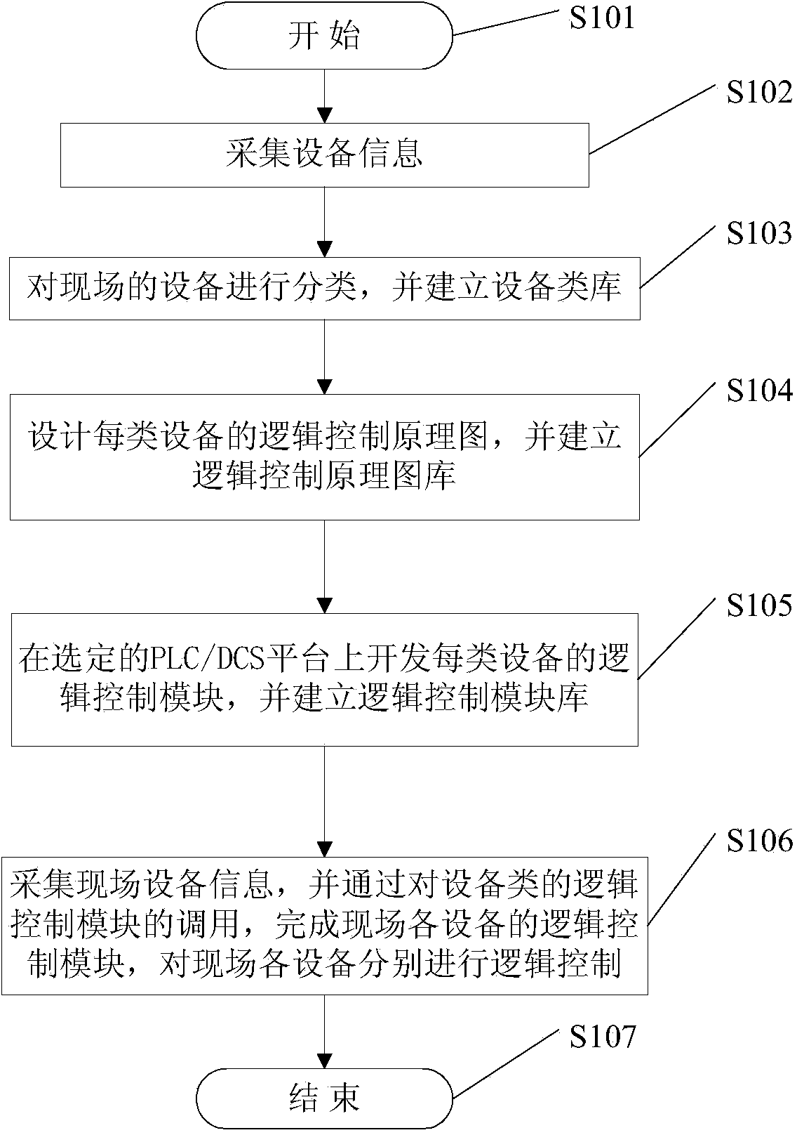
[0032] The equipment logic control method based on PLC / DCS of the present embodiment, such as figure 1 As shown, taking a foreign large-scale DCS project as an example, the control system of this project covers the whole plant and involves 18 sub-processes of the whole plant. Interlock control of fuel supply, etc. The scale of the entire control system is relatively large, with more than 11,500 I / O points, and more than 1,600 devices that need to realize logic control, including various motors, valves, and large-scale equipment. The control system adopts the PKS product of Honeywell Company. Since there are a lot of equipment involved, this implementation mode uses a typical process as an example to describe the implementation process of this implementation mode, and the specific process starts from step 101 .

[0033] In step 102, equipment infor...


PUM


Abstract

Disclosed is a device logic control method based on a programmable logic controller (PLC)/distributed control system (DCS). The method includes the steps that (1) device information is collected; (2) on-site devices are classified, and a device class library is established; (3) a logic control principle diagram of each class of devices is designed, and a logic control principle diagram library is established; (4) a logic control module of each class of devices is developed on a selected PLC/DCS platform, and a logic control module library is established; (5) on-site device information is collected, and logic control over each on-site device can be finished respectively by the logic control module of each on-site device through calling of the logic control modules of device classes. By means of the device logic control method based on the PLC/DCS, program development is accelerated, the difficulty of device logic control, program development, program testing and on-site debugging is reduced, engineering experience accumulation is facilitated, the requirement for electric professional skills of program developers is lowered, and the number of participating professional staff is decreased.

Description

technical field [0001] The invention belongs to the technical field of electrical automation, and in particular relates to a PLC / DCS-based equipment logic control method. Background technique [0002] In the process industry, the logic control of the field equipment is realized by the equipment logic control program. The traditional modular programming method is to establish corresponding subroutine modules for each device, and then the main program calls each subroutine module according to the logical relationship of the process, so as to realize the logic control of the field devices. The above-mentioned traditional modular program design and development method can realize the sharing of system resources among subprogram modules, between the subprogram module and the main program module, and can realize the parameter calling and value passing processing of the subprogram, and the processing speed is fast. For a more complex process, the program structure is more complicat...

Claims


Application Information

Patent Timeline
IPC IPC(8): G05B19/418
CPCY02P90/02
Inventor 吴永建徐文飞张杰卿丁进良郑秀萍岳恒柴天佑
Owner NORTHEASTERN UNIV
Why Eureka
Try Eureka