Sealed type switch cabinet

A switchgear, sealed technology, applied in the direction of pull-out switchgear, electric switch, switchgear, etc., can solve the complex manufacturing process, cannot meet the requirements of high-voltage switchgear's economy and reliability, and occupy Large space and other issues

Active Publication Date: 2014-09-10
袁茂银
View PDF6 Cites 6 Cited by
  • Summary
  • Abstract
  • Description
  • Claims
  • Application Information

AI Technical Summary

Problems solved by technology

The positioning device disclosed in this application and the switchgear circuit breaker handcart obtained by its application can realize the accurate guidance and left and right limit of the handcart, and can meet the stable positioning of the handcart in different positions, which can effectively reduce the loss of electric power. The acting torque can overcome the large electric force; however, it still cannot achieve the same or similar stability as that of the fixed cabinet; in addition, the circuit breaker in the cabinet generally adopts VS1 or VD4 vacuum circuit breaker, and the alignment of the dynamic and static contacts is accurate and consistent with that of the fixed cabinet. If it cannot be monitored, the structure of the contact box is not conducive to the heat dissipation of the contacts, the insulation components are easy to age, and insulation breakdown discharge accidents occur
[0006] Both of the above two switchgears have two disadvantages: they occupy a large space and the primary circuit live main components are not completely enclosed in the switchgear
The so-called solid insulation is different from the solid-sealed pole in that it not only seals the vacuum interrupter of each item, but also casts the interrupter and its related components with epoxy resin as a whole, so that the switch The safe insulation distance between the internal phases

Method used


Image

  • Sealed type switch cabinet
  • Sealed type switch cabinet
  • Sealed type switch cabinet

Examples


Embodiment Construction

[0147] The present invention will be further described in detail and completely below in conjunction with specific implementation methods and accompanying drawings.

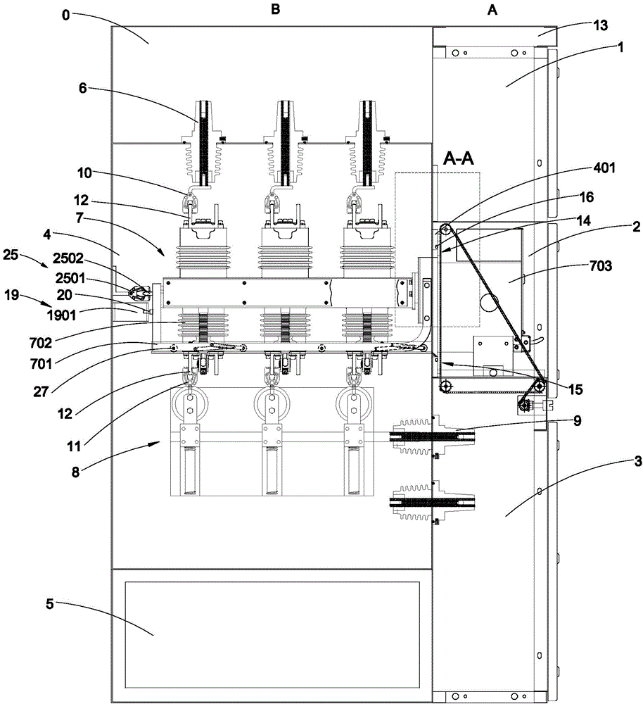
[0148] The invention provides a sealed switch cabinet, which is an indoor sealed switch cabinet, figure 1 It is a sectional view of a sealed switchgear, such as figure 1 As shown, the sealed switchgear is a floor-standing assembled cabinet structure, which includes busbar room 0, instrument room 1 (low voltage room), mechanism room 2, cable room 3, switch room 4 and pressure relief channel 5, specifically, the instrument room Room 1, mechanism room 2 and cable room 3 form the front cabinet A of the sealed switchgear, busbar room 0, switch room 4 and pressure relief channel 5 form the rear cabinet B of the sealed switch cabinet; front cabinet A and rear cabinet B The bottom is flush and placed on the ground or other planes, and the opposite cabinet walls of the front cabinet A and the rear cabinet B are attached ...


PUM


Abstract

The invention provides a sealed type switch cabinet. The sealed type switch cabinet comprises a bus chamber, an instrument chamber, a mechanism chamber, a cable chamber, a switch chamber and a pressure release channel. The instrument chamber, the mechanism chamber and the cable chamber constitute a front cabinet of the sealed type switch cabinet; the bus chamber, the switch chamber and the pressure release channel constitute a rear cabinet of the sealed type switch cabinet; the switch cabinet is successively provided with an upper wire inlet insulator set, a breaker assembly, a grounding switch and a lower wire outlet insulator set from the top to the bottom; each function chamber in the front cabinet and the rear cabinet are distributed in a stepped mode; the breaker assembly comprises a support, a breaker, an operation member and a sealing member; when the breaker assembly is disposed in the sealed type switch cabinet, the sealing member encloses the switch chamber; and the support can remove the breaker assembly out of the switch chamber and the mechanism chamber for detection and maintenance. The sealed type switch cabinet has the advantages of a fixation cabinet, a built-in handcart cabinet and an inflation cabinet, modularization design of an overall unit and a bus is realized, and the installation and maintenance are safe and simple.

Description

technical field [0001] The invention relates to a power distribution cabinet, in particular to a sealed switch cabinet, more specifically to a sealed high-voltage switch cabinet, and belongs to the technical field of electrical equipment. Background technique [0002] High-voltage switchgear is an electrical product used to realize on-off, control or protection in power system generation, transmission, distribution, power conversion and consumption. The high-voltage switch manufacturing industry is an important part of the power transmission and transformation equipment manufacturing industry, and occupies a very important position in the entire power industry. [0003] At present, the high-voltage switchgear (circuit breaker switchgear) of 6-40.5KV at home and abroad mainly includes fixed switchgear (fixed switchgear), middle-mounted or removable switchgear (handcart cabinet), inflatable switchgear (gas-filled cabinet) and Solid insulation switchgear, the above-mentioned h...

Claims


Application Information

Patent Timeline
IPC IPC(8): H02B13/00
CPCH01H2033/6667H01H3/46H01H3/32H01H33/565H02B11/00H01H9/16H02B1/052H02B1/34H02B1/565H02B11/133H02B11/167H02B11/127H02B1/36H02B11/12H02B13/045
Inventor 袁茂银
Owner 袁茂银
Why Eureka
Try Eureka