Hybrid magnetic-circuit torquer and flexible gyroscope comprising the same

A flexible gyroscope and hybrid magnetic circuit technology, which is applied in the direction of rotating gyroscopes, electrical components, electromechanical devices, etc., can solve the problems of large dynamics and high precision, and it is difficult to meet the requirements of fast use of moving carriers, etc., to achieve the realization of work The effect of rapidity requirements, improvement of successive stability accuracy, and reduction of the influence of magnetic flux leakage torque

Active Publication Date: 2014-09-10
BEIJING INST OF AEROSPACE CONTROL DEVICES
View PDF3 Cites 6 Cited by
  • Summary
  • Abstract
  • Description
  • Claims
  • Application Information

AI Technical Summary

Problems solved by technology

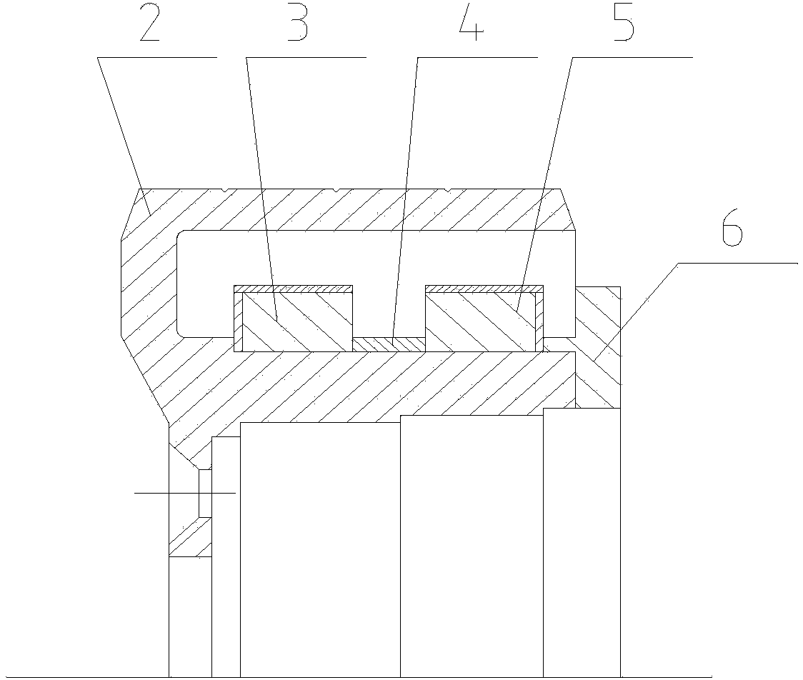
like figure 1 As shown, the existing torque device uses two sets of radially magnetized magnetic steel rings, and the flywheel assembly is composed of a flywheel 2, a first magnetic steel ring assembly 3, a magnetic isolation ring 4, a second magnetic steel ring assembly 5, and a magnetic conduction ring 6 , the magnetic field polarities of the two magnetic rings are opposite, and a magnetic circuit can be formed with the magnetic permeable ring 5, but this structure makes the moment coefficient of the flexible gyroscope k M Smaller, the dynamic measurement range is about ±200° / s, and the linearity accuracy is lower than 1×10 when the dynamic is large -3 , it is difficult to balance large dynamics and high precision; the start-up time of the gyroscope motor is more than 10s, and the stabilization time of the gyroscope takes 1h, which is difficult to meet the requirements of fast use of motion carriers

Method used


Image

  • Hybrid magnetic-circuit torquer and flexible gyroscope comprising the same
  • Hybrid magnetic-circuit torquer and flexible gyroscope comprising the same
  • Hybrid magnetic-circuit torquer and flexible gyroscope comprising the same

Examples


Embodiment Construction

[0027] The present invention will be described in further detail below in conjunction with the accompanying drawings and specific embodiments.

[0028] According to the precession principle of the flexible gyroscope, the tracking angular rate ω of the gyroscope is:

[0029] ω=M / H………………………………………(1)

[0030] In the formula (1): M—the electromagnetic control torque produced by the torque device:

[0031] H—gyroscope angular momentum;

[0032] ω—tracking angular rate.

[0033] In order to improve the tracking angular rate ω of the gyroscope and achieve a large dynamic measurement range, it can be carried out from two aspects. One is to increase the electromagnetic torque M of the torque device, and the other is to reduce the angular momentum H of the gyroscope. The relationship between the electromagnetic torque M and the coil current is:

[0034] m 电 =k M .i………………………………………(2)

[0035] In formula (2): M 电 - the electromagnetic torque generated by the energized coil under t...


PUM


Abstract

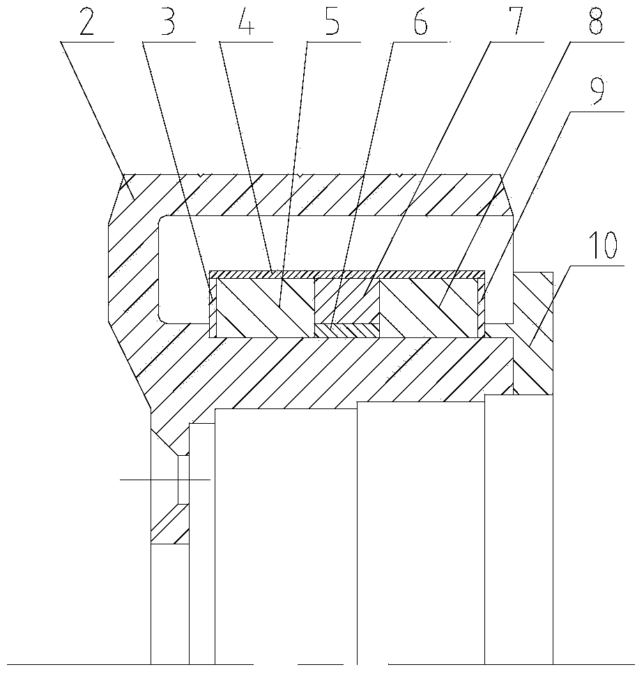
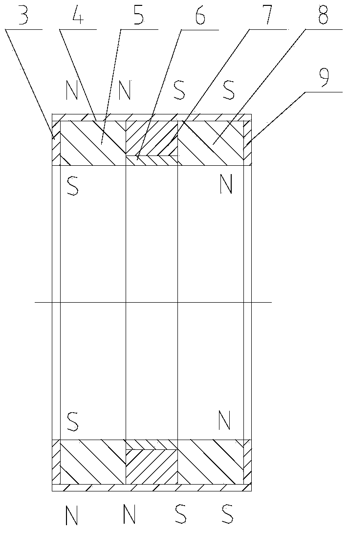
The invention discloses a hybrid magnetic-circuit torquer and a flexible gyroscope comprising the same. The hybrid magnetic-circuit torquer of the invention is a three-row magnet steel hybrid magnetic-circuit torquer, in which a three-row permanent magnet steel ring forms a moving coil portion of the torquer which is fixedly connected with a flywheel rotor to rotate at high speed, and a fixed coil of the torquer is combined with a sensor to be secured to a gyro case. As such, the magnetic flux density B of the operating airgap magnetic field is increased, and the torque coefficient of the gyroscope is also increased, resulting in a maximum tracking angle rate above 600degrees/s of the gyroscope. With the flexible gyroscope using the hybrid magnetic-circuit torquer, the gyroscope's angular momentum H is decreased by setting the rotation speed of the motor properly. A low friction torque bearing C2206094JK is used in the gyro motor in order to reduce the friction toque. Also, by reducing the operating gap between the stator and the rotor, choosing the operating site properly, and maximizing the starting torque of the driving motor, the sync time of the gyroscope is made to be less than 5S and reduced to less than 2S in a high-voltage start-up and low-voltage operation mode, so as to meet high-speed operation requirements.

Description

technical field [0001] The invention relates to a hybrid magnetic circuit torquer and a flexible gyroscope formed by using the torquer, in particular to a three-row magnetic steel hybrid magnetic circuit hybrid magnetic circuit torquer and a miniaturized large dynamic flexible gyroscope composed of the torquer. The utility model relates to a permanent gyroscope, which belongs to the technical field of mechatronics. Background technique [0002] The flexible dynamic gyroscope is a two-degree-of-freedom gyroscope. The rotor is connected to the motor drive shaft through a flexible support, and is driven by the motor to rotate at a high speed relative to the housing. When the dynamic gyroscope works at the tuning speed, the elastic restoring moment of the flexible joint can be completely offset by the dynamic rebounding moment generated by the oscillating motion of the gimbal, at this time the gyroscope rotor will stabilize in the inertial space and become unconstrained free ro...

Claims


Application Information

Patent Timeline
Patent Type & Authority Applications(China)
IPC IPC(8): H02K26/00G01C19/08
Inventor 刘朝霞关宇美郭刚蒋苏丹邹琪张敏红孙奎强朱佩霞
Owner BEIJING INST OF AEROSPACE CONTROL DEVICES
Why Eureka
Try Eureka