Method for correcting position error of permanent magnet synchronous motor rotor based on linear hall

A technology of rotor position error and permanent magnet synchronous motor, which is applied to the control of generators, motor generators, electromechanical transmissions, etc., and can solve problems such as rotor position angle error, output signal distortion, and influence on control system performance.

Active Publication Date: 2014-09-10
BEIHANG UNIV
View PDF5 Cites 17 Cited by
  • Summary
  • Abstract
  • Description
  • Claims
  • Application Information

AI Technical Summary

Problems solved by technology

However, due to the presence of high-order harmonics in the air-gap magnetic field, the output signal of the linear Hall will be distorted, causing errors in the rotor position angle and affecting the performance of the control system.

Method used


Image

  • Method for correcting position error of permanent magnet synchronous motor rotor based on linear hall
  • Method for correcting position error of permanent magnet synchronous motor rotor based on linear hall
  • Method for correcting position error of permanent magnet synchronous motor rotor based on linear hall

Examples


Embodiment Construction

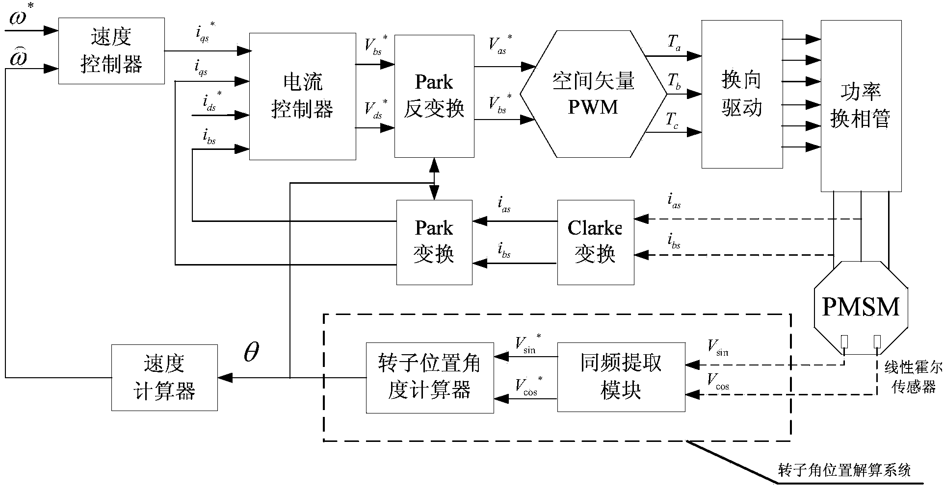
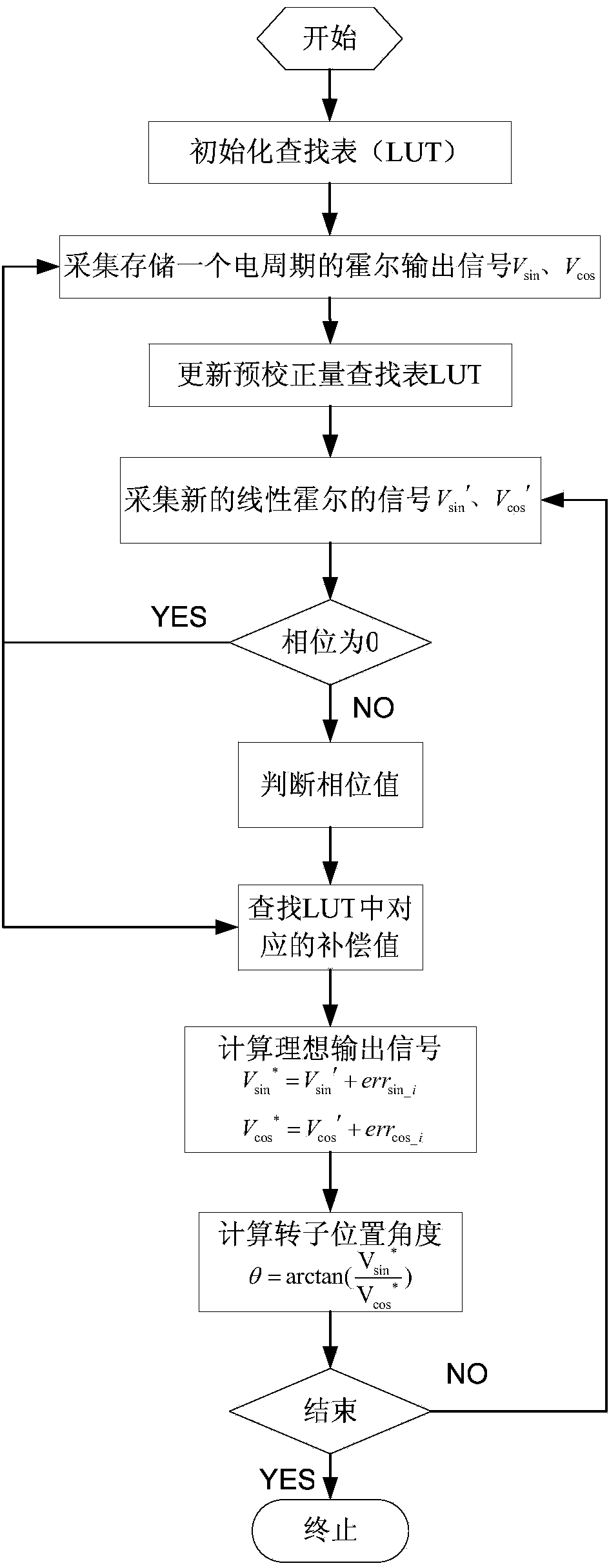
[0023] Such as figure 1 , 2 , 3, shown in 4, concrete method of the present invention is as follows:

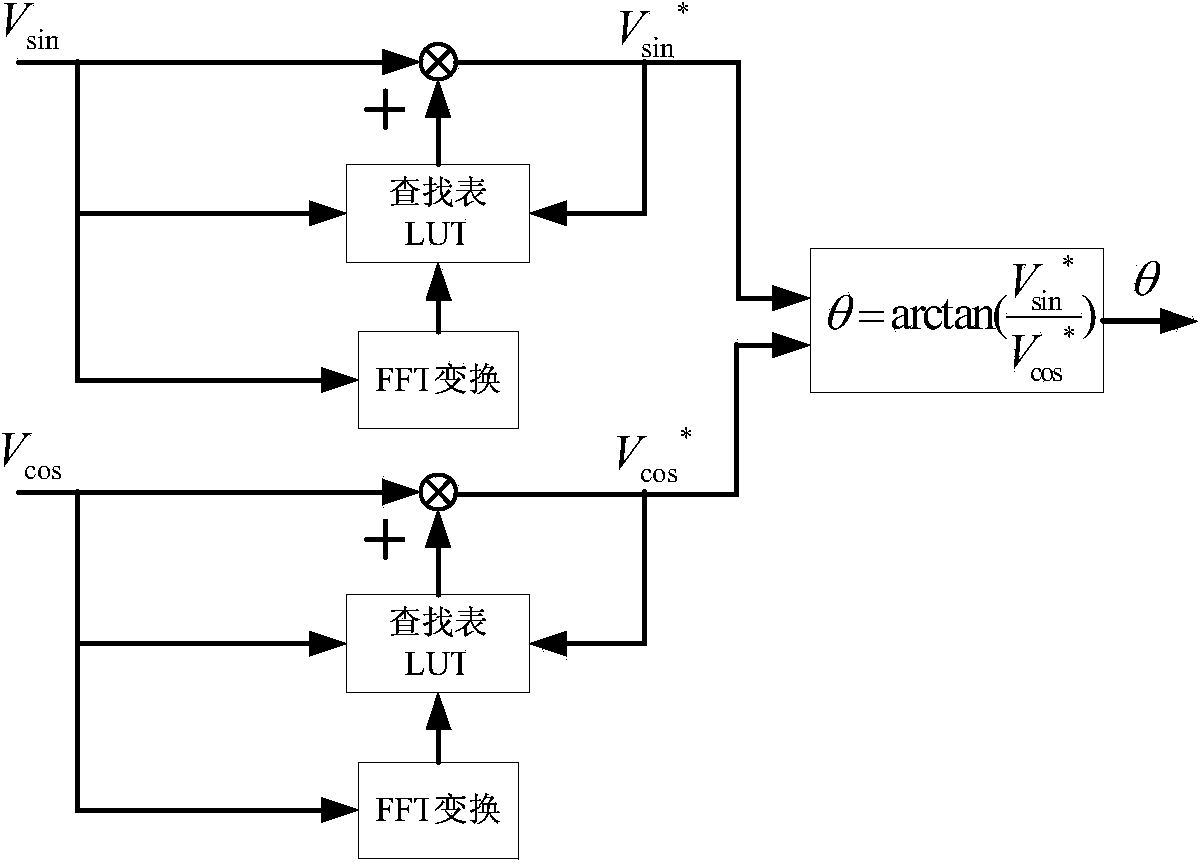
[0024] (1) if figure 1As shown, the permanent magnet synchronous motor control system based on the linear Hall sensor to which the present invention is applicable includes two linear Hall sensors whose output signals differ by 90° from each other, and their output signals are respectively V sin , V cos , collect the two linear Hall output signals V sin and V cos As a raw linear Hall signal, the signal V for one electrical cycle is stored sin , V cos , after storage ends for V sin , V cos Perform FFT transformation respectively, and the transformed signal is:

[0025] V sin = A 1 sin θ + A ...


PUM


Abstract

The invention relates to a method for correcting a position error of a permanent magnet synchronous motor rotor based on linear hall, and belongs to a method for correcting the position of the permanent magnet synchronous motor rotor. Two linear hall output signals having the difference of a 90-degrees electrical angle therebetween are acquired, fundamental components in the original signals are extracted by use of a high-precision common-frequency extraction module, and the fundamental components are fed into a rotor position angle calculator to obtain rotor angle position information. The method is characterized in that harmonics of all orders included in the original linear hall output signals are filtered out and the angle error caused by the distortions of the output signals of a linear hall position sensor can be compensated; the method is simple in algorithm, free from hardware added, easy to implement, and good in instantaneity for position signal error compensation.

Description

technical field [0001] The invention relates to a method for correcting the rotor position error of a permanent magnet synchronous motor, which can be used to compensate the error of detecting the rotor position of the permanent magnet synchronous motor based on a linear Hall sensor. Background technique [0002] Permanent magnet synchronous motors are widely used in aerospace, electric power, industrial manufacturing, instrumentation and other industrial fields. In order to realize the real-time control of permanent magnet synchronous motors, it is necessary to know the precise position of the rotor relative to the stator windings. Although there are many studies on the sensorless control strategy of permanent magnet synchronous motors. However, in these control methods, the starting problem of the motor and the running stability and control accuracy of the motor under low speed conditions have always been a difficult point. Therefore, obtaining rotor position information ...

Claims


Application Information

Patent Timeline
Patent Type & Authority Applications(China)
IPC IPC(8): H02P21/14
Inventor 郑世强宋欣达刘刚肖烨然陈宝栋
Owner BEIHANG UNIV
Why Eureka
Try Eureka