
High-power microchip laser device

A microchip laser, high-power technology, applied in the direction of lasers, laser components, phonon exciters, etc., can solve the problems of demanding laser stability, easy loss of coupling, waste of resources, etc., to facilitate the adaptation between mode fields effect, improve coupling efficiency, and improve stability

Active Publication Date: 2014-09-17
广东华快光子科技有限公司 +1
View PDF5 Cites 3 Cited by
  • Summary
  • Abstract
  • Description
  • Claims
  • Application Information

AI Technical Summary

Problems solved by technology

[0004] 1. The coupling efficiency of signal light and pump light is low, resulting in waste of resources;
[0005] 2. The laser has strict requirements on the stability of the working environment, and the external disturbance is easy to lose the coupling, which brings great difficulties to the industrial application of the laser

Method used


Image

  • High-power microchip laser device
  • High-power microchip laser device
  • High-power microchip laser device

Examples


Embodiment Construction

[0022] The features of the present invention and other related features will be further described in detail below in conjunction with the accompanying drawings through embodiments, so as to facilitate the understanding of those skilled in the art:

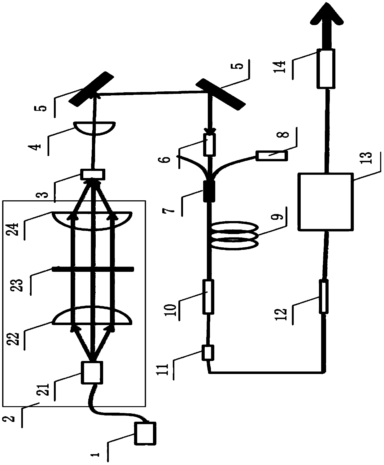
[0023] Such as figure 1 As shown, a high-power microchip laser device includes a first pump light source 1 connected in sequence, an optical coupling system 2, a passive Q-switched microchip 3, a convex lens 4 for focusing output, a reflector 5, and a first A collimator 6 and a beam combiner 7, the beam combiner 7 is provided with a collimation input end, a pump light input end, and a beam combination output end, and the beam combiner 7 collimates the input end and the first collimator The output end of the beam combiner 6 is connected to the output end of the beam combiner 7, and the pump light input end of the beam combiner 7 is connected to a second pump light source 8, and the output end of the beam combiner 7 is connected to a...


PUM

PropertyMeasurementUnit
Core diameteraaaaaaaaaa

Abstract

The invention discloses a high-power microchip laser device. The high-power microchip laser device is characterized by comprising a first pump light source, an optical coupling system, a passive Q switched microchip, a convex lens for focus output, a reflector, a first collimator and a beam binder all of which are connected in sequence, the beam binder is provided with a collimation input end, a pump light input end and a beam binding output end, the collimation input end of the beam binder is connected with the output end of the first collimator, the pump light input end of the beam binder is connected with a second pump light source, and the beam binding output end of the beam binder is sequentially connected with a small-core-diameter double-cladding gain optical fiber used for laser pre-amplification, a pumping leakage device, an optical fiber isolator, an optical fiber mode field adapter, a large-core-diameter multi-mode double-cladding optical fiber amplifier for primary laser amplification, and a second collimator used for performing output. The high-power microchip laser device can operate under the full optical fiber condition, the working stability of the whole high-power microchip laser device is greatly improved, and the high-power microchip laser device can meet the industrial application condition.

Description

[technical field] [0001] The invention relates to a high-power microchip laser device. [Background technique] [0002] The growing market demand for high-precision micromachining puts forward higher requirements on the peak power and repetition frequency of laser pulses, and nanosecond pulse lasers generally cannot meet the requirements of fine processing. Most of the high-power lasers working in the picosecond region in the past were mode-locked systems, and were used for high-precision micromachining after reducing the repetition rate and amplifying them. Usually, the mode-locked oscillator needs to be combined with a pulse picker and passed through a regenerative amplifier, which often results in a bulky, complex and expensive system. Ultrashort pulse fiber lasers with low cost, high stability and high gain amplification have attracted widespread attention. These advantages are especially important for industrial materials processing lasers. [0003] In 1994, at the Ma...

Claims


Application Information

Patent Timeline
IPC IPC(8): H01S3/067H01S3/091H01S3/10
Inventor 张志刚刘关玉朱海波周亮云志强
Owner 广东华快光子科技有限公司
Learn More