A phase-locked loop frequency correction method and system
A frequency correction and phase-locked loop technology, applied in the field of communication, can solve problems such as time pressure and long correction time
- Summary
- Abstract
- Description
- Claims
- Application Information
AI Technical Summary
Problems solved by technology
Method used
Image
Examples
Embodiment 1
[0122] see Figure 4a , which is a flow chart of Embodiment 1 of the PLL frequency correction method provided by the present invention.
[0123] The PLL frequency correction method provided in this embodiment is applied to sub-band selection of a multi-band voltage-controlled oscillator; including:
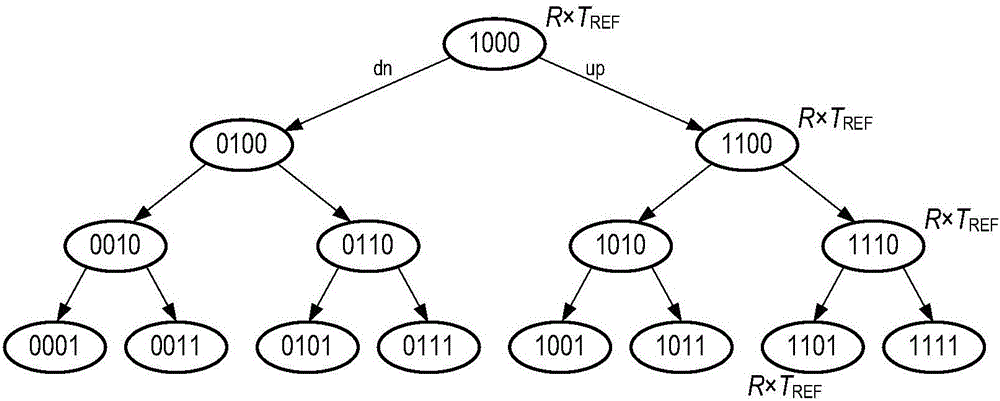
[0124] S401a: At counting time T CNT [k], carry out frequency counting on the frequency signal output by the voltage-controlled oscillator under the current working sub-band, and obtain the frequency count value FCNT[k], wherein the current working sub-band corresponds to the current node in the binary search tree binary value;
[0125] It should be noted that frequency counting of the frequency signal output by the voltage-controlled oscillator in the current working sub-band is performed by a frequency counter.
[0126] It can be understood that, for a multi-band voltage-controlled oscillator, its current working sub-band refers to the binary value corresponding to the curren...
Embodiment 2
[0133] see Figure 4 , which is a flow chart of Embodiment 2 of the PLL frequency correction method provided by the present invention.
[0134] The broadband phase-locked loop frequency correction method provided in this embodiment includes:
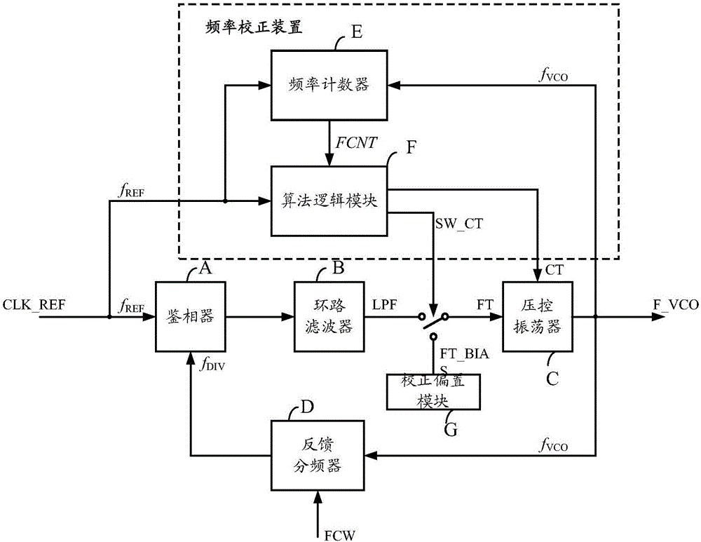
[0135] S401: at the current counting time T CNT [k], judge the current count value FCNT[k] output by the frequency counter and the corresponding current target frequency count value FCNT TARGET Whether the error of [k] is less than a predetermined value; the frequency counter counts the output frequency of the voltage-controlled oscillator; the T CNT [k]=T REF*R[k]; the FCNT TARGET [k]=R[k]×FCW; the voltage-controlled oscillator is a multi-band voltage-controlled oscillator; sub-band selection in the multi-band voltage-controlled oscillator is controlled by a digital signal; that is, CT is a digital signal.
[0136] Among them, T REF For the period of phase-locked loop input reference clock; R[k] is counting time parameter, is the ...
Embodiment 3
[0180] see Image 6 , which is a flow chart of Embodiment 3 of the PLL frequency correction method provided by the present invention.
[0181] This embodiment introduces a most complete correction process.
[0182]It has been introduced that R[k] is a positive integer in the first method embodiment, because in practical applications, for the convenience of implementation, R[k] can be set to the form of an integer power of 2, because in the logic circuit, it is only necessary to perform The shift operation can realize the calculation of the integer power of 2, which can greatly reduce the consumption of chip resources. Therefore, in this embodiment, R[k] is realized by an integer power of 2.
[0183] S601: at the current counting time T CNT Under [k], read the current count value FCNT[k] of the frequency counter;
[0184] S602: Calculate the current target frequency count value FCNT TARGET [k]; S603: by FCNT[k] and FCNT TARGET [k] Get the error FCNT of both ERR =FCNT[k]-...
PUM
 Abstract
Description
Claims
Application Information
 - R&D
- Intellectual Property
- Life Sciences
- Materials
- Tech Scout
- Unparalleled Data Quality
- Higher Quality Content
- 60% Fewer Hallucinations
Browse by: Latest US Patents, China's latest patents, Technical Efficacy Thesaurus, Application Domain, Technology Topic, Popular Technical Reports.
© 2025 PatSnap. All rights reserved.Legal|Privacy policy|Modern Slavery Act Transparency Statement|Sitemap|About US| Contact US: help@patsnap.com


