Ecological roof for rainwater utilization and air purification

An air purification and ecological technology, which is applied in the field of rainwater resource utilization and air purification, can solve the problems of resource waste, achieve the effects of prolonging life, reducing urban heat island effect, and blocking electromagnetic radiation

Active Publication Date: 2014-09-24
HARBIN INST OF TECH
View PDF11 Cites 13 Cited by
  • Summary
  • Abstract
  • Description
  • Claims
  • Application Information

AI Technical Summary

Problems solved by technology

Moreover, roof rainwater is quickly discharged into the sew

Method used


Image

  • Ecological roof for rainwater utilization and air purification
  • Ecological roof for rainwater utilization and air purification
  • Ecological roof for rainwater utilization and air purification

Examples


specific Embodiment approach 1

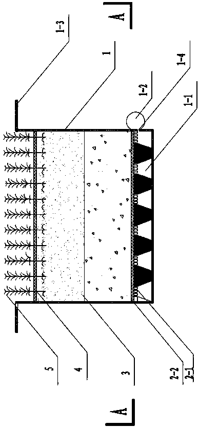
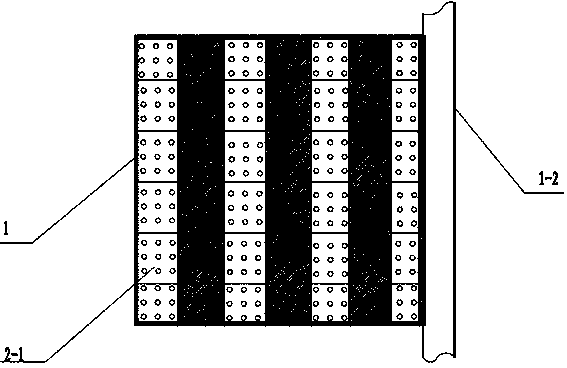
[0025] Specific implementation mode one: as figure 1 and figure 2 As shown, the wetland ecosystem module provided by this embodiment is composed of a water storage and drainage structure tray 1 , a root growth control layer 2 , a plant growth substrate layer 3 , a dustproof protection filter layer 4 , and a vegetation layer 5 .

[0026] 1. The water storage and drainage structure tray 1 is located on the existing roof and is a rectangular tank with anti-seepage, water storage and drainage control functions. It is generally PVC board or concrete structural material, and the thickness of the board is 0.8-10mm; The size is 1m (L) × 1m (B) × 0.5m (H); the interior of the bottom of the water storage and drainage structure tray 1 is arranged with water storage and drainage grooves 1-1, and the water storage and drainage grooves 1- 1 is a trapezoidal structure, the grooves are arranged in a network, and the size is: 1m (length), 12cm×6cm×6cm (the upper bottom, lower bottom, and hei...

specific Embodiment approach 2

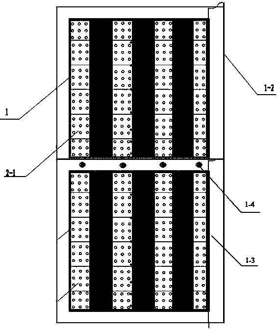
[0033] Embodiment 2: The rainwater utilization and air purification ecological roof described in this embodiment is composed of several wetland ecosystem modules. Such as figure 2 As shown, taking two modules as an example, the modules are connected by screws 1-4 along 1-3 along the top of the waterproof, water-retaining, and drainage structure tray 1, and the drainage pipes 1-2 between the modules pass through The flange connection constitutes the drainage pipe network, and the water pipes are fixed on the roof through pipe hoops.

[0034] In field operations, any roof must be installed with anti-seepage membrane to test the effect of anti-seepage. After reaching the standard, install the root growth control layer.

[0035] The installation process is as follows: first use asphalt to fix the water storage and drainage structure tray 1, and at the same time use screws 1-4 to connect the water storage and drainage structure tray 1, use flanges to connect the water collection ...

specific Embodiment approach 3

[0036] Specific embodiment three: In this embodiment, the water storage and drainage structure tray 1 is fixed on the roof by asphalt sticking, and is installed according to the originally designed drainage slope, maintaining the original slope.


PUM

PropertyMeasurementUnit
Thicknessaaaaaaaaaa
Thicknessaaaaaaaaaa
Particle sizeaaaaaaaaaa

Abstract

The invention discloses an ecological roof for rainwater utilization and air purification. The ecological roof comprises a plurality of wetland ecosystem modules, wherein each wetland ecosystem module is composed of a tray with water storage and water drainage structures, a root growth control layer, a plant growth matrix layer, a dustproof protection and filtering layer and a vegetation stratum. Water storage and water drainage grooves are formed inside the bottoms of the tray with the water storage and water drainage structures, water collecting pipes are arranged on the outer portions of the bottoms of the tray with the water drainage structures, and the water storage and water drainage grooves are connected with the water collecting pipes. The root growth control layer is located on the water storage and water drainage grooves. The plant growth matrix layer is located on the root growth control layer. The dustproof protection and filtering layer is located on the plant growth matrix layer. The vegetation stratum is located on the dustproof protection and filtering layer. A roof ecological system can effectively utilize rainwater, filter and clean air, improve air quality, reduce the urban heat island effect, save energy, reduce consumption, block electromagnetic radiation, and build and protect the diversity of an ecological system.

Description

technical field [0001] The invention belongs to the technical field of rainwater resource utilization and air purification, and relates to a new generation of ecological buildings based on the ecological utilization and air purification system of roof rainwater. Background technique [0002] Since the beginning of the 20th century, the global urbanization level has soared from 15% at the beginning of the century to 50% at the end of the century, and the 21st century is even known as the "century of cities". An important feature of urbanization is the increase in the area of ​​impermeable floors and roofs. Buildings with non-water roofs replace woodland and farmland with good water permeability, resulting in increased urban surface runoff, shortened confluence time, reduced water stagnation capacity of the watershed, accelerated confluence speed, and reduced the original ability of the watershed to flatten the flood waveform. The flood waveform becomes sharper than before th...

Claims


Application Information

Patent Timeline
IPC IPC(8): E04D13/00E04D13/04A01G1/00E03B3/02
CPCY02A20/108Y02A30/254Y02A30/60Y02B80/32
Inventor 王丽付嘉峰王琳孔祥荣霍玉鑫李浩然
Owner HARBIN INST OF TECH
Why Eureka
Try Eureka