Eureka AIR delivers breakthrough ideas for toughest innovation challenges, trusted by R&D personnel around the world.

External deformation fatigue test loading device for web clearance plane between vertical stiffening rib and wing plate

A fatigue test and loading device technology, which is applied in the direction of applying stable tension/pressure to test the strength of materials, and achieves the effects of accurate fatigue test results, simplified structure, and easy disassembly.

Active Publication Date: 2014-09-24
CHANGAN UNIV
View PDF4 Cites 8 Cited by
  • Summary
  • Abstract
  • Description
  • Claims
  • Application Information

AI Technical Summary

Problems solved by technology

[0004] Aiming at the deficiencies of the existing steel bridge out-of-deck deformation fatigue test technology, the present invention proposes a method that can truly simulate the effect of the cross brace on the stiffener in the real bridge, so that the stress behavior at the web gap in the fatigue test piece is consistent with that of the real bridge. Consistent, reliable and accurate test results, low requirements for the test site and loading tonnage, simple operation, convenient disassembly, and low test cost The loading device for out-of-plane deformation fatigue test of the vertical stiffener and the web gap between the flange

Method used


Image

  • External deformation fatigue test loading device for web clearance plane between vertical stiffening rib and wing plate
  • External deformation fatigue test loading device for web clearance plane between vertical stiffening rib and wing plate
  • External deformation fatigue test loading device for web clearance plane between vertical stiffening rib and wing plate

Examples


Embodiment 1

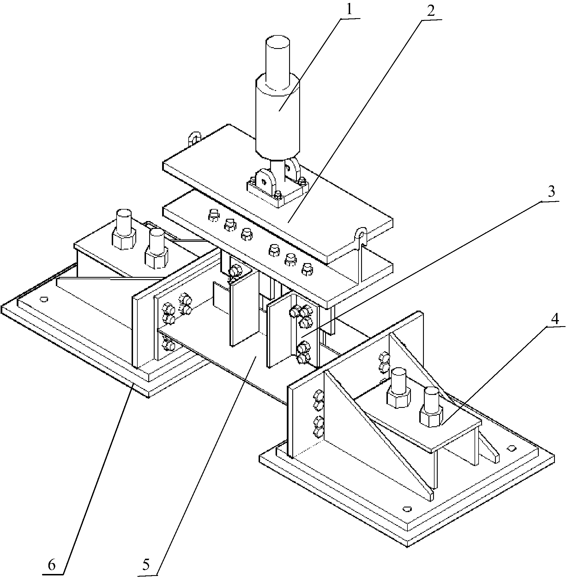
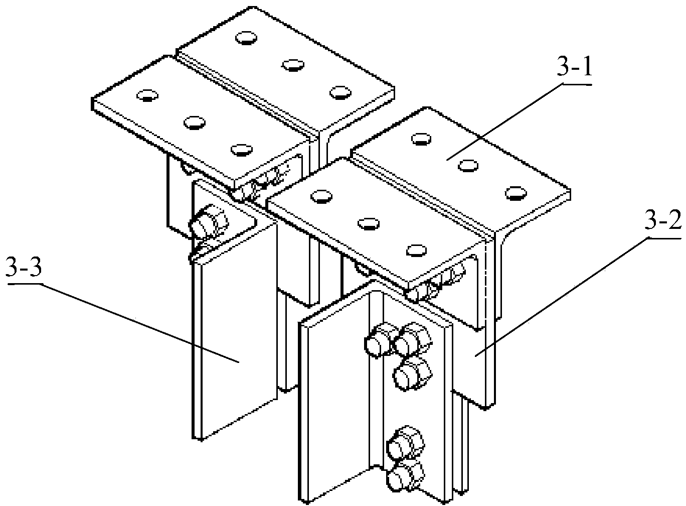
[0023] Such as figure 1 As shown, the loading device for the out-of-plane deformation fatigue test of the web gap between the vertical stiffener and the wing plate of this embodiment is composed of a servo hydraulic actuator 1, a loading beam 2, a connection assembly 3, a ground anchor 4, and a concrete leveling layer 6 composition.

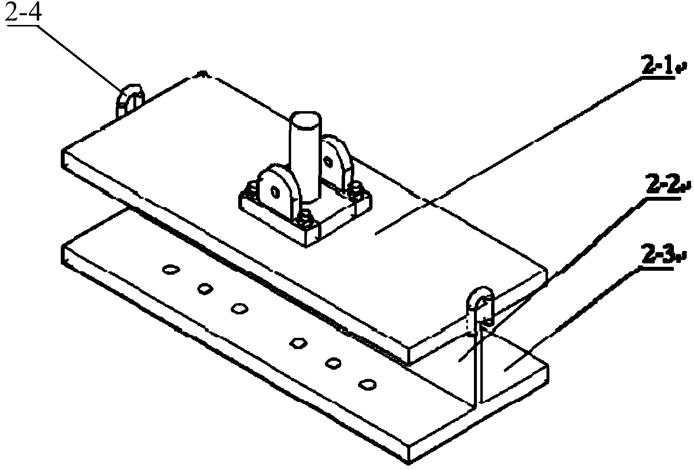
[0024] The loading beam 2 of this embodiment is an I-shaped beam welded from steel plates, see figure 2 The upper flange plate 2-1 is a rectangular steel plate with a width of 400mm, a thickness of 40mm, and a length of 1000mm. The load beam web 2-2 is a rectangular steel plate with a width of 200mm, a thickness of 20mm, and a length of 1000mm. The lower wing The edge plate 2-3 is a rectangular steel plate with a width of 400mm, a thickness of 40mm, and a length of 1000mm. In order to temporarily fix the loading beam 2 on the reaction frame, the left and right ends of the upper flange 2-1 of the loading beam 2 are welded with loops 2-4 made of thic...

Embodiment 2

[0033] The upper flange plate 2-1 of the loading beam 2 in this embodiment is a rectangular steel plate with a width of 250 mm, a thickness of 16 mm, and a length of 500 mm. The load beam web 2-2 is a width of 100 mm, a thickness of 12 mm, and a length of 500 mm. For rectangular steel plates, the geometry and size of the lower flange plate 2-3 and the upper flange plate 2-1 are the same.

[0034] The horizontal top plate of the steel anchor box 4-1 of this embodiment is a rectangular plate with a width of 250 mm, a thickness of 18 mm, and a length of 300 mm, and the vertical wing plate is a rectangular plate with a width of 150 mm, a thickness of 16 mmm, and a length of 400 mm.

[0035] The other components and their connection relationship are the same as in the first embodiment.

Embodiment 3

[0037] The upper flange plate 2-1 of the loading beam 2 of this embodiment is a rectangular steel plate with a width of 550mm, a thickness of 60mm and a length of 1500mm. The web 2-2 of the loading beam is a width of 500mm, a thickness of 24mm, and a length of 1500mm. For rectangular steel plates, the geometry and size of the lower flange plate 2-3 and the upper flange plate 2-1 are the same.

[0038] The horizontal top plate of the steel anchor box 4-1 of this embodiment is a rectangular plate with a width of 400 mm, a thickness of 24 mm, and a length of 800 mm, and the vertical wing plate is a rectangular plate with a width of 450 mm, a thickness of 22 mmm, and a length of 600 mm.

[0039] The other components and their connection relationship are the same as in the first embodiment.


PUM

PropertyMeasurementUnit
widthaaaaaaaaaa
thicknessaaaaaaaaaa
lengthaaaaaaaaaa

Abstract

The invention relates to an external deformation fatigue test loading device for a web clearance plane between a vertical stiffening rib and a wing plate. Two ground anchors for fixing a test piece are oppositely arranged on a concrete leveling layer. The test piece is connected with a loading beam through a connecting assembly. The loading beam is an H-shaped beam. The middle of an upper flange plate is connected with a servo hydraulic actuator. According to the external deformation fatigue test loading device, the test piece is fixed to the ground anchors through high-strength bolts, the servo hydraulic actuator provides two concentrated cyclic loads for the web vertical stiffening rib through the loading beam and the connecting assembly, and the acting force of a cross strut in a steel plate girder bridge on the web stiffening rib can be truly simulated; in addition, due to reasonable simplification, the scale of the test piece is reduced, the test space is saved, the structure is simplified, the requirement for loading shipping tons is reduced, the test piece is high in replaceability and easy to disassemble, a large number of variable parameter tests can be conveniently and economically carried out, and the application prospect is wide.

Description

Technical field [0001] The invention belongs to the technical field of bridge engineering, and particularly relates to the technical field of bridge engineering test, in particular to a fatigue test loading device for the deformation of the web gap between a vertical stiffener and a wing plate. Background technique [0002] The fatigue problem of steel bridges seriously affects the service life of the bridge. Research shows that about 90% of fatigue cracking problems in steel bridges are caused by out-of-plane deformation or secondary stress at fatigue-sensitive details. In the design of the steel bridge, the transverse connection between the main girder is realized by the connection of the vertical stiffeners welded between the transverse bracing and the main girder web. In order to avoid the vertical stiffener and the main girder tension flange Welding details have fatigue failure, and there is usually a web gap of tens of millimeters between the vertical stiffener and the main...

Claims


Application Information

Patent Timeline
Patent Type & Authority Applications(China)
IPC IPC(8): G01N3/12
Inventor 王春生翟慕赛全先凯段兰王茜闫生龙孙宇佳魏孟春
Owner CHANGAN UNIV
Why Eureka
Eureka Blog
Learn More