
Signal Analyzer For Nuclear Magnetic Flowmeters

A technology of a signal analyzer and a measuring device, applied in the field of signal analyzers, can solve problems such as inability to reliably measure crude oil share, and achieve the effects of reducing production costs, reducing production costs, and improving analysis and processing

Active Publication Date: 2014-09-24
KRONE GMBH
View PDF6 Cites 4 Cited by
  • Summary
  • Abstract
  • Description
  • Claims
  • Application Information

AI Technical Summary

Problems solved by technology

However, the test separator was not able to reliably measure fractions of crude oil smaller than 5% compared to NMR flow measurement devices

Method used


Image

  • Signal Analyzer For Nuclear Magnetic Flowmeters

Examples


Embodiment Construction

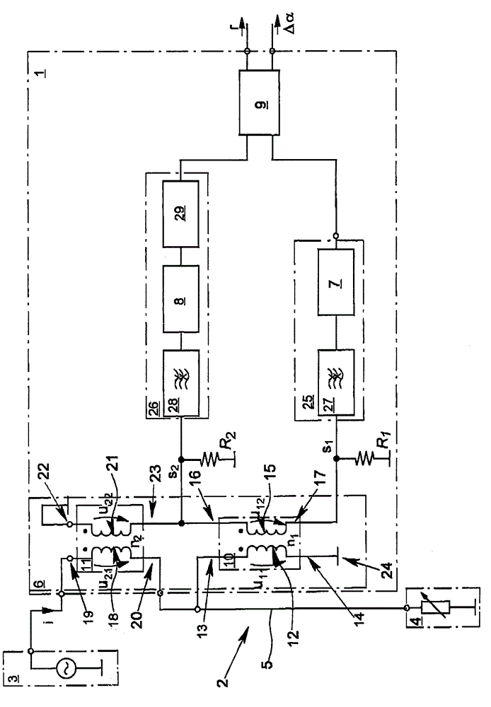
[0019] A signal analyzer 1 is arranged in a power signal path 2 between a signal generator 3 for generating an electrical excitation signal and an electrical load 4 . The transmission of the electrical excitation signal takes place via the power signal line 5 located in the power signal path 2 . The signal analyzer 1 comprises an output coupling circuit 6 for output coupling a first signal s representing an excitation signal incident on the load 4 1 and for output coupling a second signal s representing the portion of the excitation signal reflected on the load 4 2 . Furthermore, the signal analyzer 1 comprises a first attenuator 7 and a second attenuator 8, as well as a detector 9 for determining the second signal s 2 The magnitude of the first signal s with respect to the 1 ratio of the magnitude r and for determining the first signal s 1 with the second signal s 2 The phase difference Δα.

[0020] The output coupling circuit 6 of the signal analyzer 1 according to the...


PUM


Abstract

A signal analyzer for nuclear magnetic flowmeters is provided. The signal analyzer can be placed in a power signal path between a signal generator that generates an electric excitation signal and an electrical load. The signal analyzer includes a power signal line in the power signal path for the transmission of electrical signals. The signal analyzer also includes a decoupling circuit for decoupling a first signal characterizing the excitation signal occurring in the load and for decoupling of a second signal characterizing the part of the excitation signal reflected at the load. The signal analyzer further includes a first attenuator and a second attenuator. Additionally, the signal analyzer includes a detector for determining the ratio of the magnitude of the first signal to the magnitude of the second signal and for determining the phase difference between the first signal and the second signal.

Description

technical field [0001] The invention proposes a signal analyzer, in particular for a nuclear magnetic flow measuring device, for a power signal path arranged between a signal generator for generating an electrical excitation signal and an electrical load In the above, the signal analyzer: has a power signal line in the power signal path for transmitting electrical signals; has an output coupling circuit for output coupling to characterize the excitation incident into the load A first signal of a signal and a second signal for output coupling characterizing the portion of the excitation signal reflected on the load; having a first attenuator and a second attenuator, and having a detector for Determining a ratio of the magnitude of the first signal to the magnitude of the second signal and for determining a phase difference between the first signal and the second signal. Background technique [0002] The nucleus of an element having nuclear spin also has a magnetic moment ind...

Claims


Application Information

Patent Timeline
Patent Type & Authority Applications(China)
IPC IPC(8): G01R33/54
CPCG01R33/36G01F1/716G01N24/081G01N24/08G01R33/563
Inventor B.邓克J.J.J.霍夫斯泰德S.I.吕克
Owner KRONE GMBH
Learn More